Flashlight that can be focused

a flashlight and focus technology, applied in the field of flashlights, can solve the problems of involuntarily shifting the relative position between the lamp head or the reflector and the light source, and permanent shaking

Active Publication Date: 2015-07-21
ZWEIBRUDER OPTOELECTRONICS BGMH & CO KG
View PDF6 Cites 1 Cited by
  • Summary
  • Abstract
  • Description
  • Claims
  • Application Information

AI Technical Summary

Benefits of technology

[0017]Lastly, according to a further embodiment the clamping device is formed by multiple clamping elements that engage in grooves of a locking element. The locking element preferably takes the form of a pin and is part of a connecting piece that is connected to the casing. According to a preferred embodiment of the invention, the clamping elements have a recess through which the locking element engages, wherein part surfaces of the clamping elements are held in the grooves of the locking element and thus in an engaged position by the force of a spring. The springs are preferably integrally connected to the clamping elem...

Problems solved by technology

However, it is a disadvantage of such a flashlight that it is intended for the adjustment of the relative position between the lamp head and the light source to be as smooth as possible, but this has the consequence that the relative position between the lamp head or the re...

Method used


Image

  • Flashlight that can be focused
  • Flashlight that can be focused
  • Flashlight that can be focused

Examples


Embodiment Construction

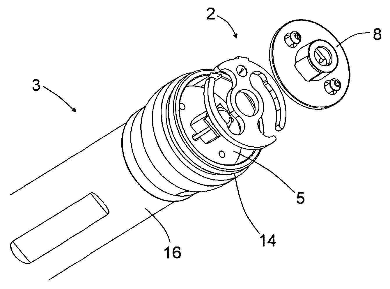
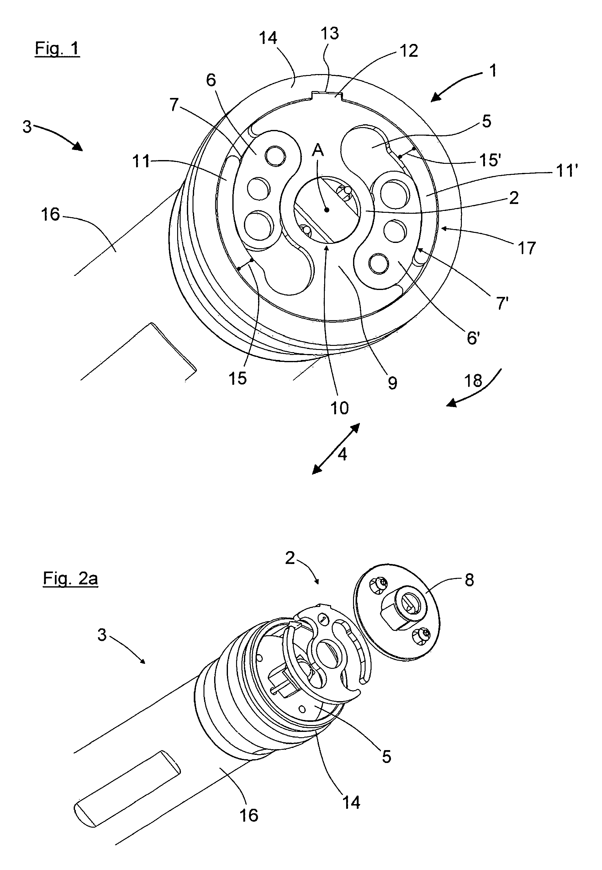
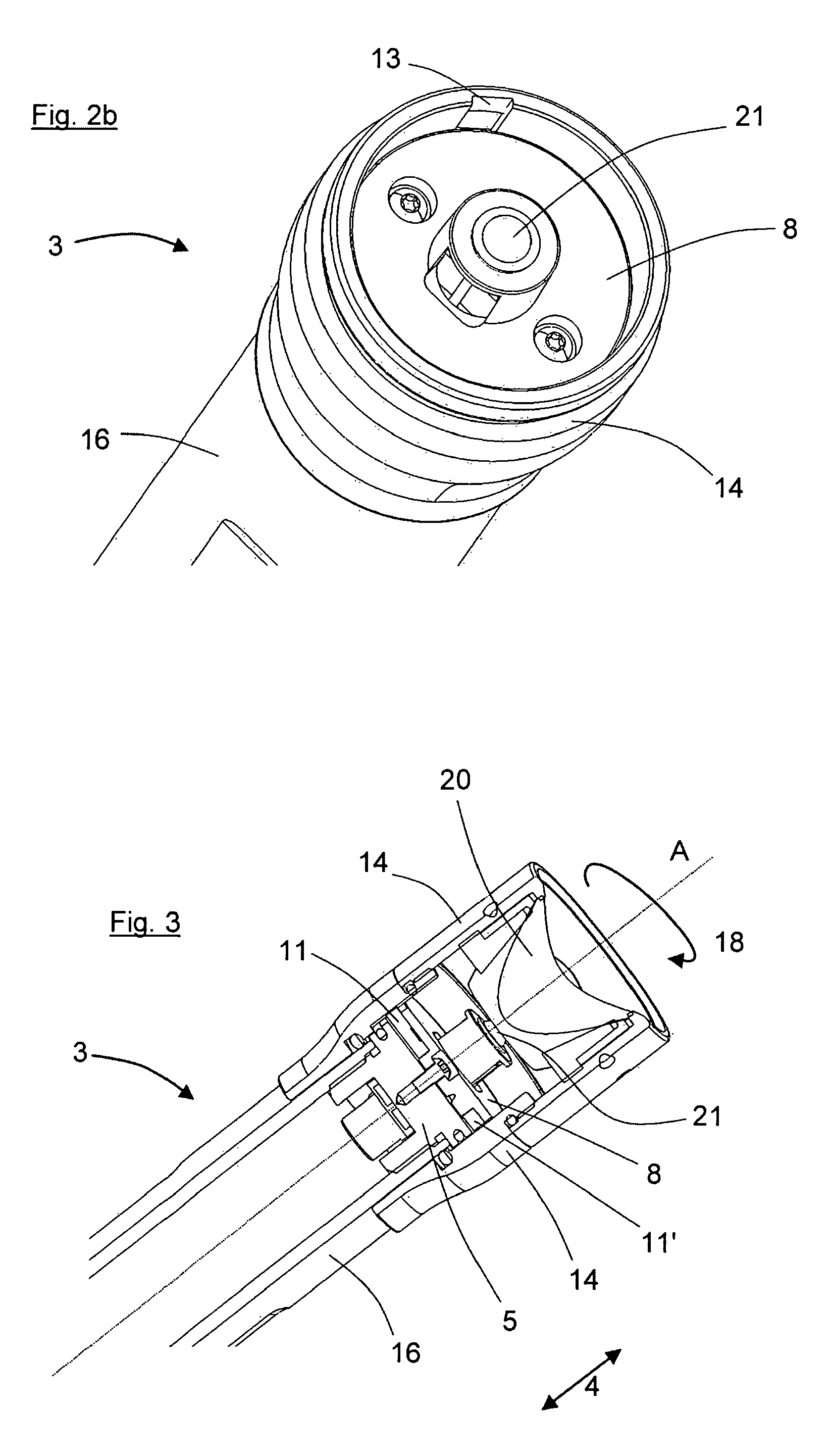
[0026]According to a concrete embodiment of the present invention, the clamping device 1 has a clamping body 2 that is mounted so that it can rotate about the longitudinal axis A of the flashlight 3. The clamping body 1 here bears against a base plate 5 at the center of which a light source, preferably an LED 21, is arranged. Moreover, two kidney-shaped elements 6, 6′ that fulfill two functions are arranged on the base plate 5. On the one hand, the outer surfaces of the kidney-shaped elements 6, 6′ are designed as upward-sloping surfaces 7, 7′. On the other hand, the kidney-shaped elements 6, 6′ serve as spacers for a cover plate 8 (see FIG. 2) that covers the clamping device 1 from the lens attachment 20.

[0027]The clamping body 2 essentially consists of a web 9 arranged along the diameter of the flashlight 3, a central recess 10 being provided for the passage of the LED 21. Two clamping elements 11, 11′ that bear against the upward-sloping surfaces 7, 7′ are pivotably arranged radi...


PUM


Abstract

The present invention relates to a flashlight having a casing, a light source and a lamp head with a lens attachment that can be displaced longitudinally axially relative to the light source in order to focus the emitted cone of light. The object of the present invention is to provide a flashlight that, on the one hand, enables the reflector to be displaced smoothly relative to the light source and, on the other hand, prevents involuntary shifting of the focusing that has been set. According to the invention, the flashlight has a clamping device for fixing the lamp head in a selectable longitudinal axial position.

Description

CROSS REFERENCE TO RELATED APPLICATIONS[0001]This application is the US-national stage of PCT application PCT / DE2011 / 001148 filed 25 May 2011 and claiming the priority of PCT patent application PCT / DE2011 / 001148 itself filed 25 May 2011 and German patent application 202011109155.8 itself filed 15 Dec. 2011.FIELD OF THE INVENTION[0002]The present invention relates to a flashlight with a casing, a light source, and a lamp head having a lens attachment that can be displaced longitudinally axially relative to the light source in order to focus the emitted cone of light.BACKGROUND OF THE INVENTION[0003]Flashlights of this type are already known from the prior art. A lamp is described, for example, in DE 29 50 850 [U.S. Pat. No. 4,307,439] that emits an essentially parallel light beam when the filament is at the focal point of the paraboloid of the reflector. The beam can be altered by displacing the bulb and the battery casing axially relative to the lamp head and the reflector. Such an ...

Claims


Application Information

Patent Timeline
IPC IPC(8): F21L4/04F21V17/02F21V1/00F21L4/00F21L4/02F21V15/01F21V14/06F21Y101/02
CPCF21L4/04F21L4/005F21L4/027F21L4/045F21L15/02F21V14/065F21V15/01F21V17/02F21Y2101/02F21Y2115/10
Inventor OPOLKA, RAINER
Owner ZWEIBRUDER OPTOELECTRONICS BGMH & CO KG
Why Eureka
Try Eureka