
Talbot imaging devices and systems

a technology of imaging devices and systems, applied in the field of wide field of view and high resolution imaging devices, can solve the problems that many on-chip microscopes cannot achieve optical resolution, and achieve the effect of large lateral translational shift of talbot images

Active Publication Date: 2015-07-21
CALIFORNIA INST OF TECH
View PDF103 Cites 29 Cited by
  • Summary
  • Abstract
  • Description
  • Claims
  • Application Information

AI Technical Summary

Benefits of technology

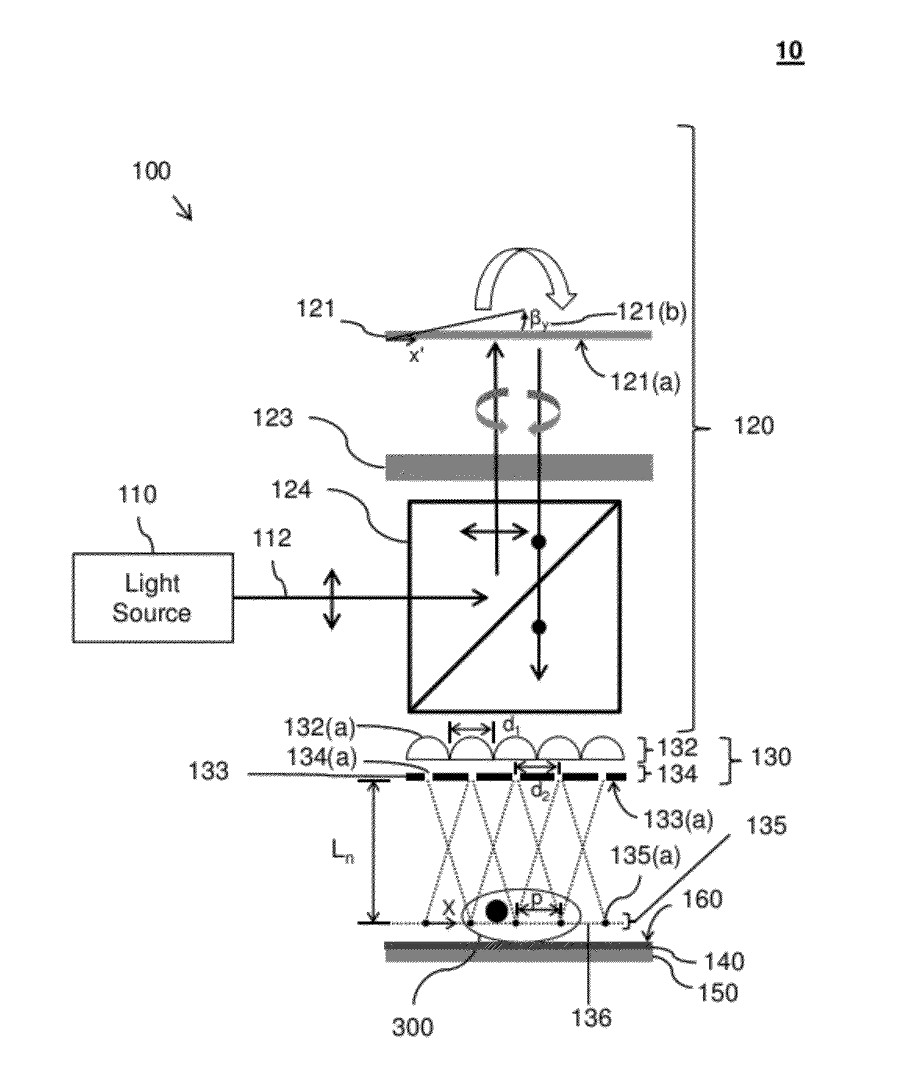
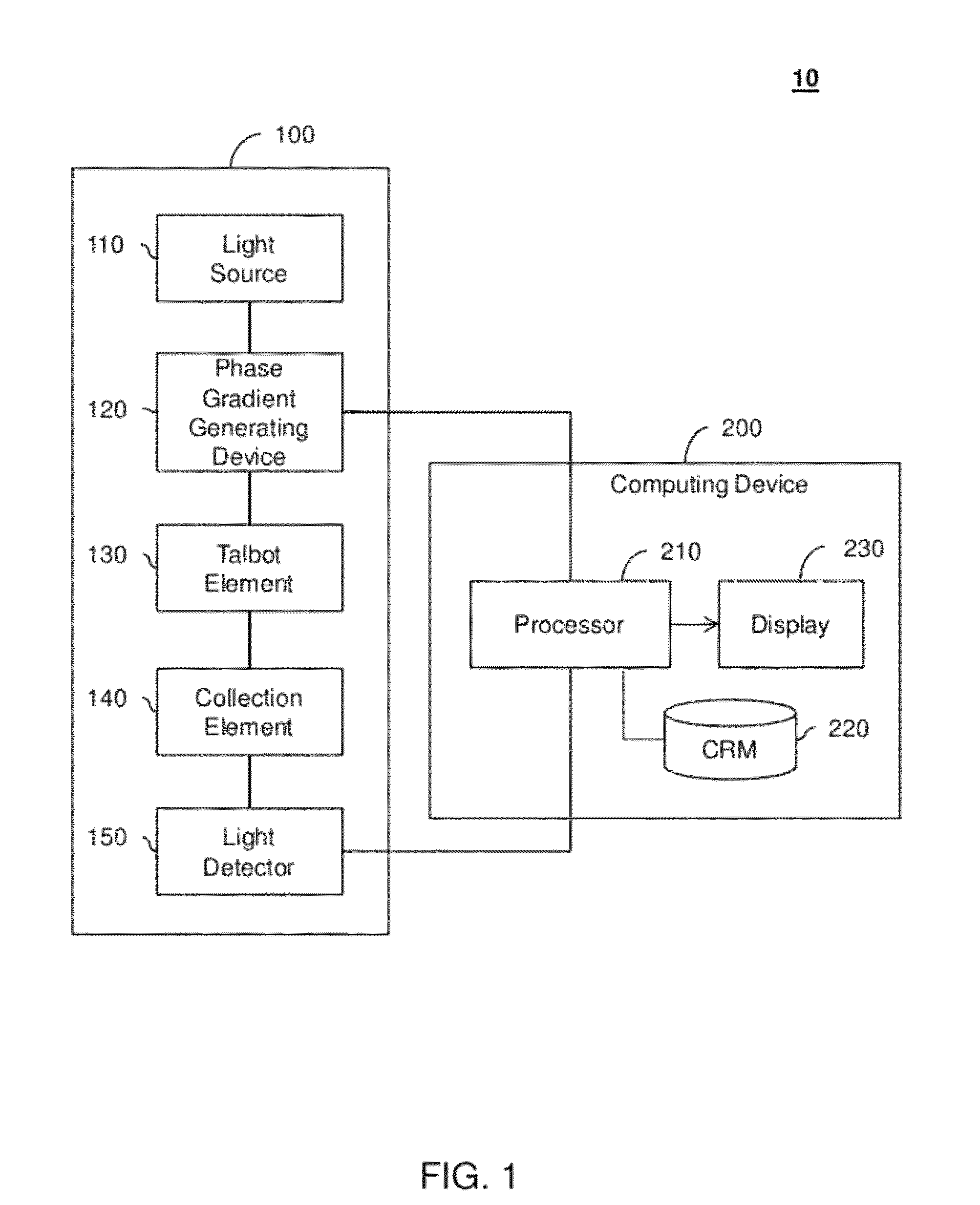
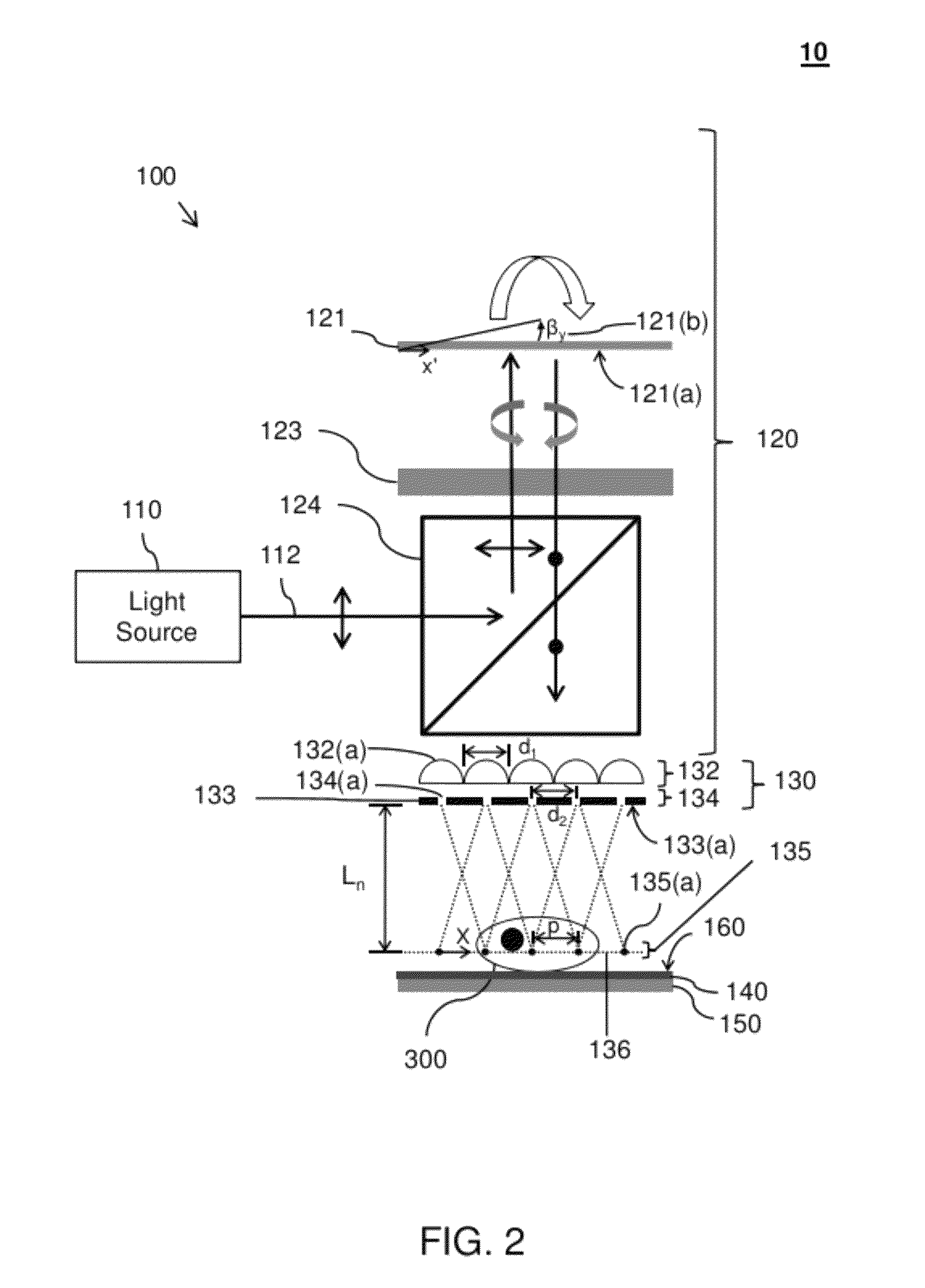
The present invention is related to a device called a Ti system, which uses a Talbot element to create an image of an object. The device has a system for generating a small change in the phase of light, which results in a shift of the Talbot image when the light is directed through a small gap. As the workpiece is scanned, the light detector captures the changes caused by the object, and an image of the object can be created based on these changes. The device also has a collection element to filter out unwanted light. Overall, this invention allows for improved imaging capabilities and the creation of fluorescence images.

Problems solved by technology

Many on-chip microscopes cannot achieve the optical resolution in fluorescence imaging comparable to that achievable by a convention microscope.

Method used


Image

  • Talbot imaging devices and systems
  • Talbot imaging devices and systems
  • Talbot imaging devices and systems

Examples


Embodiment Construction

[0024]Embodiments of the present invention will be described below with reference to the accompanying drawings. Some embodiments include a Ti system having a Ti device and a processor. The Ti device includes a Talbot element, a phase gradient generating device, and a light detector. The Talbot element repeats a Talbot image (e.g., array of focal spots) at a plane at a distance of an integer multiple of a half Talbot distance, nlt—2, from itself. A small linear phase gradient change of the incident light field can induce a relatively large lateral translational shift of the Talbot image. The phase gradient generating device can scan the Talbot image over an object at the plane by changing the phase gradient of the light field incident the Talbot element over time. As the Talbot image is scanned over the object, the light detector captures time varying light data associated with light altered by the object. The processor receives one or more signals with the time varying light data fr...


PUM


Abstract

Talbot imaging systems comprising a Talbot element, a phase gradient generating device, a light detector, and a processor. The Talbot element repeats a Talbot image at a distance from the Talbot element. The phase gradient generating device scans the Talbot image at a plane at the distance from the Talbot element by incrementally changing a phase gradient of a light field incident the Talbot element. As the Talbot image is scanned, the light detector captures time varying data associated with light altered by an object located at the distance from the Talbot element. The processor reconstructs an image of the object based on the time-varying light data.

Description

CROSS-REFERENCES TO RELATED APPLICATIONS[0001]This is a non-provisional application of, and claims priority to, U.S. Provisional Patent Application No. 61 / 450,718 entitled “Fluorescence / Bright Field Talbot Microscope,” filed on Mar. 9, 2011. This provisional application is hereby incorporated by reference in its entirety for all purposes.[0002]This non-provisional application is related to the following commonly-assigned patent applications, which are hereby incorporated by reference in their entirety for all purposes:[0003]U.S. patent application Ser. No. 12 / 903,650 entitled “Holographically Illuminated Imaging Devices” filed on Oct. 13, 2010.STATEMENT AS TO RIGHTS TO INVENTIONS MADE UNDER FEDERALLY SPONSORED RESEARCH OR DEVELOPMENT[0004]This invention was made with government support under Grant No. W81XWH-09-1-0051 awarded by the US Army Medical Research and Material Command and Grant No. AI096226 awarded by the National Institutes of Health. The government has certain rights in ...

Claims


Application Information

Patent Timeline
Patent Type & Authority Patents(United States)
IPC IPC(8): H01L27/146G02B5/18G02B21/36G02B21/06
CPCG02B5/1842G02B21/06G02B21/367
Inventor PANG, SHUOYANG, CHANGHUEI
Owner CALIFORNIA INST OF TECH
Learn More