Apparatus and method to generate X-rays by contact electrification

a technology of contact electrification and apparatus, applied in the direction of electrical apparatus, x-ray tubes, electric discharge tubes, etc., can solve problems such as reliability, wear, and out-gassing that occurs

Active Publication Date: 2015-07-21
TRIBO LABS +1
View PDF7 Cites 4 Cited by
  • Summary
  • Abstract
  • Description
  • Claims
  • Application Information

AI Technical Summary

Benefits of technology

[0010]An x-ray imaging system according to an embodiment of the current invention includes an x-ray source, and an x-ray detector. The x-ray source includes an enclosing vessel, a first roller arranged at least partially within the enclosing vessel, a second roller arranged at least partially within the enclosing vessel and to be in rolling contact with the first roller, and a drive assembly operatively connected to at least one of the first and second rollers. The drive assembly causes the first and second rollers to rotate while in contact to bring portions of the first and second rollers into and out of contact within the enclosing vessel as the first and second rollers rotate. The first roller has a surface at least partially of a first triboelectric material and the second roller has a surface at least partially of a second triboelectric material, the first triboelectric material having a negative triboelectric potential relative to the second triboelectric material. The enclosing vessel is structured to provide a controlled atmospheric environment, and the first triboelectric material, the second triboelectric material and the controlled atmospheric environment are selected such that rolling contact between the first and second rollers produces x-rays.

Problems solved by technology

26, 1 (1966)) and meets both criteria, a disadvantage of using these for a portable X-ray device not requiring a high voltage supply is, however, the significant out-gassing that occurs during peeling off-the-shelf tape in vacuo (E. Constable, J. Horvat and R. A. Lewis, Appl. Phys. Lett. 97, 131502 (2010)) as well as practical issues such as reliability, wear, etc.

Method used


Image

  • Apparatus and method to generate X-rays by contact electrification
  • Apparatus and method to generate X-rays by contact electrification
  • Apparatus and method to generate X-rays by contact electrification

Examples


examples

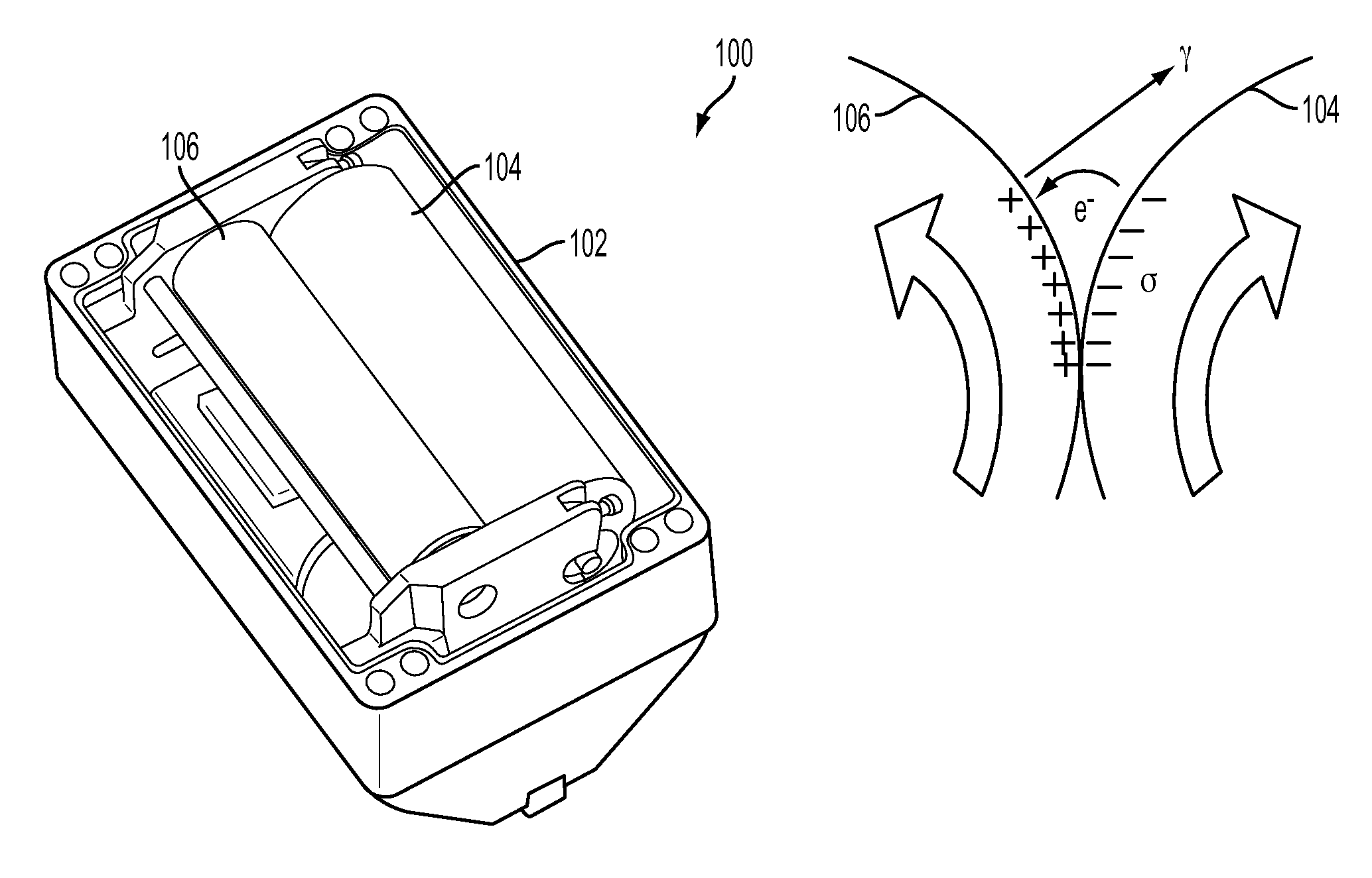
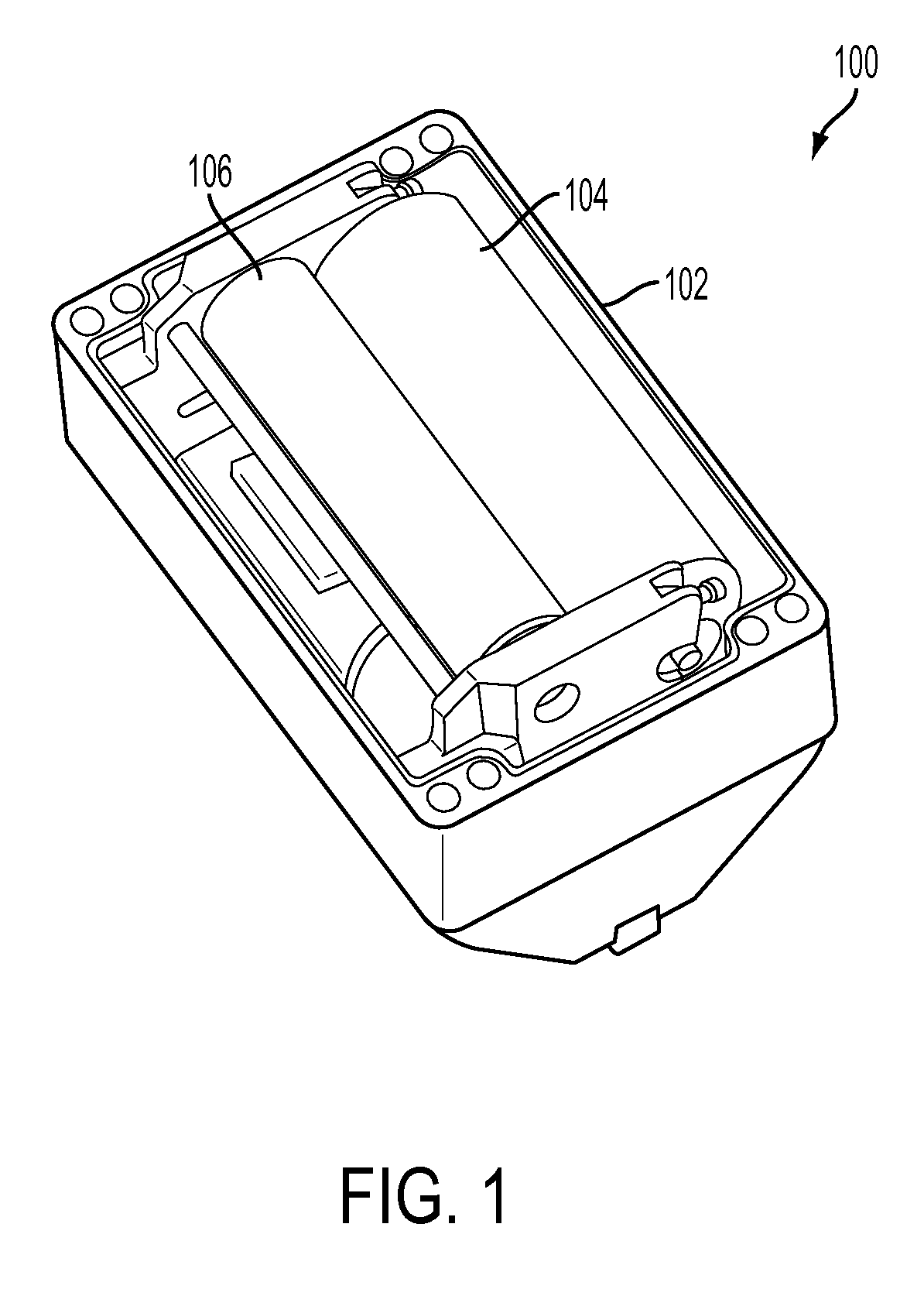
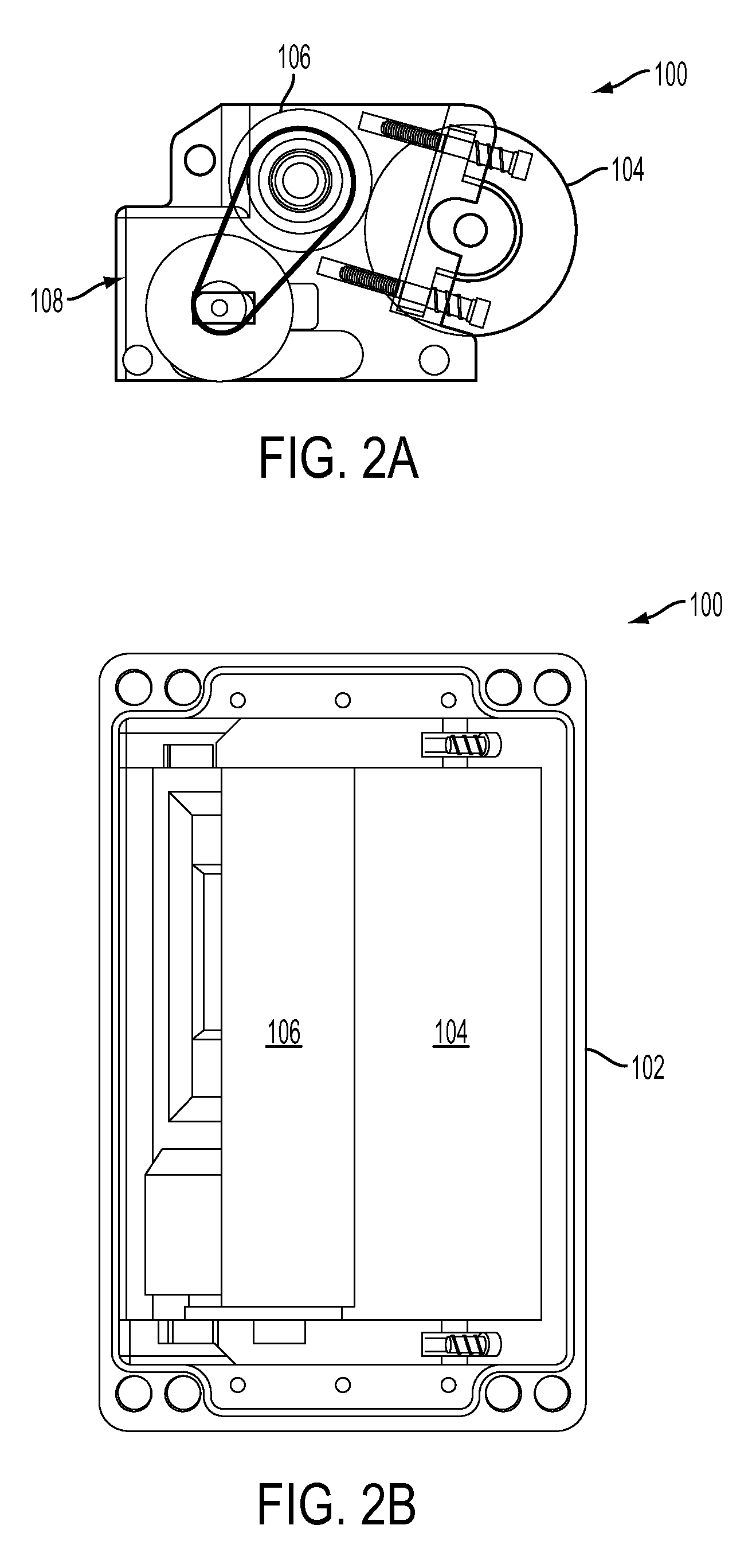
[0042]In an example, two rollers of different materials were selected to exchange and hold charge after contact. They can be pressed into contact by an external force, such as, but not limited to springs. A source of mechanical motion such as but not limited to an electric motor brings the surfaces into relative motion. A particular example of this embodiment is given by a roller with a metallic surface in contact with a polymer roller. The x-ray emission from such a system rotating in a vessel held at a pressure of 1×10⁻³ Torr of air is provided in FIG. 7.

[0043]The x-ray flux from contacting rotating rollers can be controlled by the rotation speed (FIG. 8) and it is proportional to the rotation speed up to a tangential velocity of 80 cm / s (see, Inset, FIG. 8) according to an embodiment of the current invention. This speed corresponds to a rotation speed of 200 rpm. In general, the x-ray flux scales with the area of material that is brought into and out of contact per second. For co...


PUM


Abstract

An x-ray source includes an enclosing vessel, a first roller arranged at least partially within the enclosing vessel, a second roller arranged at least partially within the enclosing vessel and to be in rolling contact with the first roller, and a drive assembly operatively connected to at least one of the first and second rollers. The drive assembly causes the first and second rollers to rotate while in contact to bring portions of the first and second rollers into and out of contact within the enclosing vessel as the first and second rollers rotate. The first roller has a surface at least partially of a first triboelectric material and the second roller has a surface at least partially of a second triboelectric material, the first triboelectric material having a negative triboelectric potential relative to the second triboelectric material. The enclosing vessel is structured to provide a controlled atmospheric environment, and the first triboelectric material, the second triboelectric material and the controlled atmospheric environment are selected such that rolling contact between the first and second rollers produces x-rays.

Description

CROSS-REFERENCE OF RELATED APPLICATION[0001]This is a national stage application under 35 U.S.C. §371 of PCT / US2012 / 036310 filed May 3, 2012, the entire contents of which are incorporated herein by reference and this application claims priority to U.S. Provisional Application No. 61 / 482,031 filed May 3, 2011, the entire contents of which are hereby incorporated by reference.[0002]This invention was made with Government support under W81XWH-10-1-1049, awarded by the United States Army Medical Research and Materiel Command. The Government has certain rights in the invention.BACKGROUND[0003]1. Field of Invention[0004]The field of the currently claimed embodiments of this invention relates to triboelectric x-ray sources and systems.[0005]2. Discussion of Related Art[0006]Triboelectricity has been utilized in fundamental scientific research as a source of high electrostatic potential for over three centuries from the early electrostatic apparatus of Haukesbee (F. Haukesbee, Physico-Mecha...

Claims


Application Information

Patent Timeline
Patent Type & Authority Patents(United States)
IPC IPC(8): H01J35/00H05G2/00
CPCH05G2/00H05G1/02
Inventor CAMARA, CARLOSPUTTERMAN, SETH J.HIRD, JONATHAN
Owner TRIBO LABS
Why Eureka
Try Eureka