Supercharge Your Innovation With Domain-Expert AI Agents!

Vehicle and vehicle control method

a technology for vehicles and control methods, applied in the direction of process and machine control, electric control for exhaust treatment, instruments, etc., can solve the problem of unnecessary consumption of energy, and achieve the effect of suppressing wasteful energy consumption

Inactive Publication Date: 2015-07-28
TOYOTA JIDOSHA KK
View PDF21 Cites 0 Cited by
  • Summary
  • Abstract
  • Description
  • Claims
  • Application Information

AI Technical Summary

Benefits of technology

The patent describes a system that controls the temperature of a vehicle's catalyst based on the vehicle's speed and the amount of electric power being supplied to the vehicle. This allows for optimal catalyst temperature control during both vehicle travel and power receiving, reducing energy waste and improving overall efficiency.

Problems solved by technology

However, if the catalyst is warmed up in a similar manner between the case where the engine is operated at the time when the generator is driven and the case where the engine is operated at the time when the vehicle is travelling, energy may be unnecessarily consumed.

Method used


Image

  • Vehicle and vehicle control method
  • Vehicle and vehicle control method
  • Vehicle and vehicle control method

Examples


Embodiment Construction

[0028]Hereinafter, an embodiment of the invention will be described with reference to the accompanying drawings. In the following description, like reference numerals denote the like components. The names and functions of those components are also the same. Thus, the detailed description thereof will not be repeated.

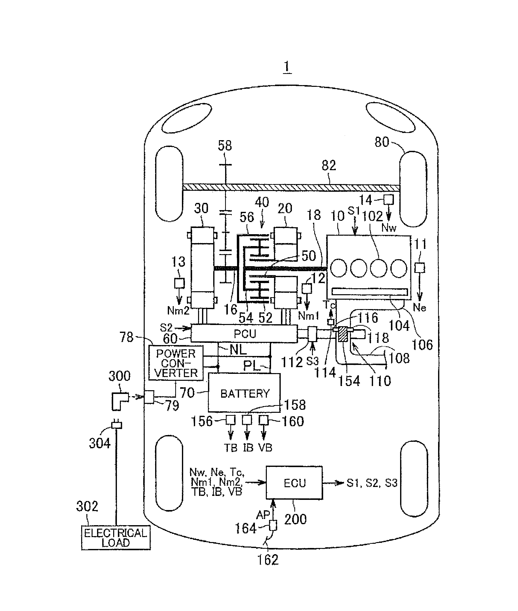
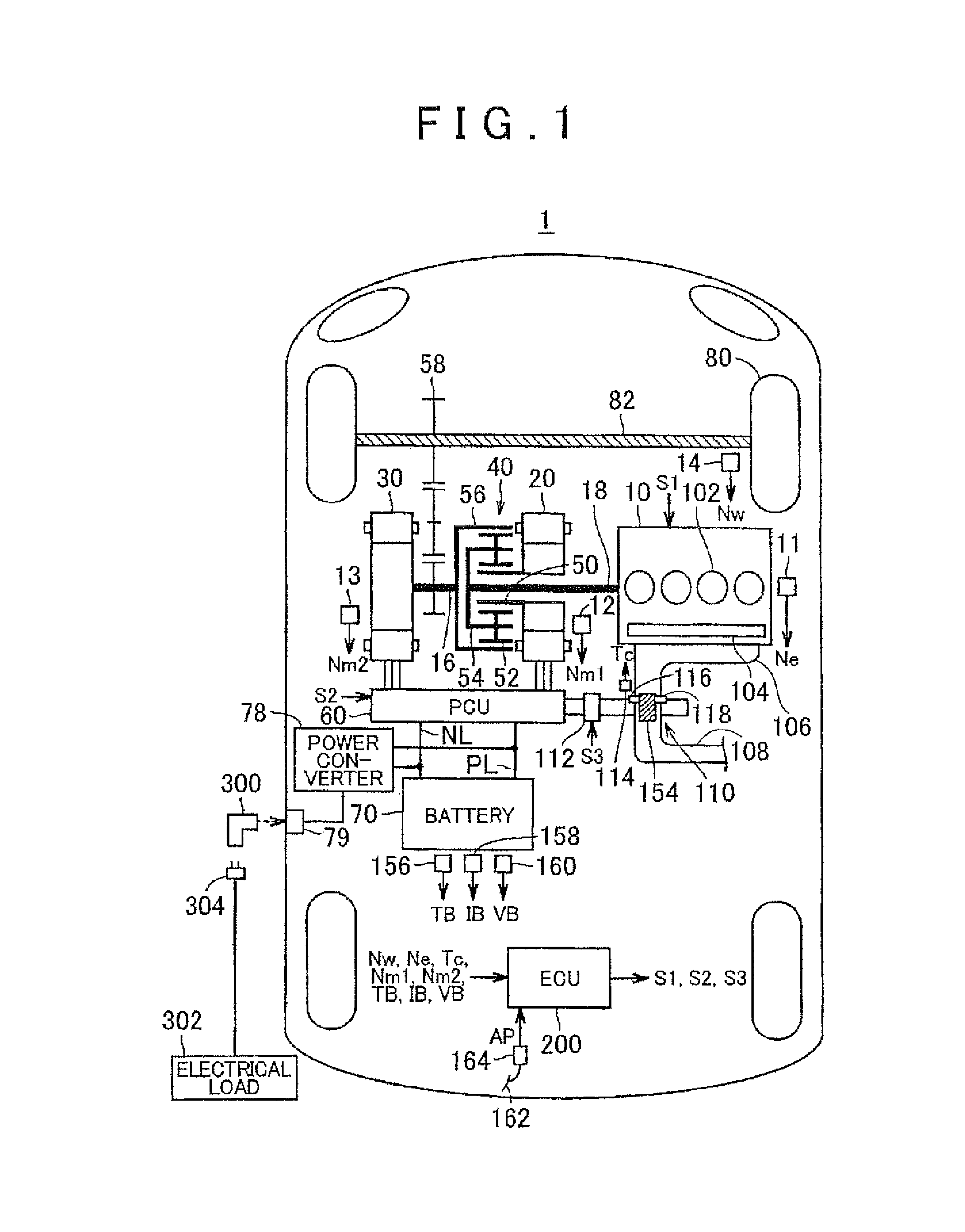
[0029]The overall block diagram of a hybrid vehicle 1 (in the following description, simply referred to as vehicle 1) according to the present embodiment will be described with reference to FIG. 1. The vehicle 1 includes an engine 10, a drive shaft 16, a first motor generator (or a first rotating electrical machine, hereinafter, referred to as first MG) 20, a second motor generator (or a second rotating electrical machine, hereinafter, referred to as second MG) 30, a power split unit 40, a speed reducer 58, a power control unit (PCU) 60, a battery 70, a power converter 78, a socket 79, drive wheels 80 and an electronic control unit (ECU) 200.

[0030]The vehicle 1 travels b...


PUM


Abstract

A vehicle includes: an electrical storage device configured to supply electric power to a power receiving system outside the vehicle; a power generating device configured to supply electric power to the electrical storage device and the power receiving system; an engine that is a power source of the power generating device and that has a catalyst for purifying exhaust gas; and a control device. The control device is configured to control the vehicle such that a catalyst temperature becomes a first target value when there is a request to warm up the catalyst while the vehicle is travelling, and the control device configured to control the vehicle such that catalyst temperature becomes a second target value different from the first target value when there is a request to warm up the catalyst while electric power is being supplied to the power receiving system.

Description

INCORPORATION BY REFERENCE[0001]The disclosure of Japanese Patent Application No 2012-111416 filed on May 15, 2012 including the specification, drawings and abstract is incorporated herein by reference in its entirety.BACKGROUND OF THE INVENTION[0002]1. Field of the Invention[0003]The invention relates to a vehicle that includes an engine and a power generating device that is able to supply electric power to a device outside of the vehicle, and a vehicle control method.[0004]2. Description of Related Art[0005]Japanese Patent Application Publication No, 2001-231106 (JP 2001-231106 A) describes a vehicle that supplies electric power to an external load by driving a generator with the use of an engine.[0006]A catalyst provided in an exhaust pipe of the engine needs to be warmed up such that the temperature of the catalyst falls within a predetermined temperature range required to purify exhaust gas. However, if the catalyst is warmed up in a similar manner between the case where the en...

Claims


Application Information

Patent Timeline
Patent Type & Authority Patents(United States)
IPC IPC(8): B60W20/00B60K6/445B60W10/06F01N9/00B60L50/16
CPCB60W20/00B60K6/445B60W10/06B60W20/1082B60W2510/244B60W2710/0694Y02T10/6239Y10S903/903B60W20/16Y02T10/62
Inventor MITSUTANI, NORITAKE
Owner TOYOTA JIDOSHA KK
Features
  • R&D
  • Intellectual Property
  • Life Sciences
  • Materials
  • Tech Scout
  • Unparalleled Data Quality
  • Higher Quality Content
  • 60% Fewer Hallucinations
Learn More