
Indoor wireless energy transmission system and wireless energy transmission method

An indoor wireless and energy transmission technology, used in transportation and packaging, electric vehicles, electrical components, etc., can solve problems such as equipment interference, security threats, and inability to wirelessly transmit electrical and electronic equipment, and reduce computational complexity and costs. Effect

Active Publication Date: 2017-06-16
SOUTH CHINA UNIV OF TECH
View PDF4 Cites 24 Cited by
  • Summary
  • Abstract
  • Description
  • Claims
  • Application Information

AI Technical Summary

Problems solved by technology

[0007] The purpose of the present invention is to solve the problem of being unable to wirelessly transmit energy to multiple stationary / moving electrical and electronic equipment at the same time in an indoor environment, causing interference to equipment that does not need to be charged, and affecting humans, animals, plants, and equipment that do not need to be charged in the energy transmission space To solve the problem of security threats, a wireless energy transmission system and wireless energy transmission method with high transmission efficiency, low interference and high security are proposed

Method used


Image

  • Indoor wireless energy transmission system and wireless energy transmission method
  • Indoor wireless energy transmission system and wireless energy transmission method
  • Indoor wireless energy transmission system and wireless energy transmission method

Examples


Embodiment Construction

[0040] In order to better understand the present invention, the present invention will be further described below in conjunction with the accompanying drawings, but the embodiments of the present invention are not limited thereto.

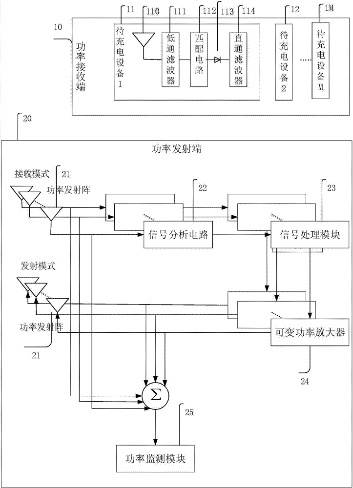
[0041] like figure 1 As shown, an indoor wireless energy transmission system includes a power receiving end 10 and a power transmitting end 20; the power transmitting end 20 is composed of a power transmitting array 21, a signal analysis circuit 22, a signal processing module 23, a variable power amplifier 24 and a power monitoring Module 25 is made up; Wherein the combination of signal analysis electric circuit 22, signal processing module 23, variable power amplifier 24 and power monitoring module 25 is called data processing station; The power transmission array of receiving mode and information analysis circuit 22, signal processing module 23, The variable power amplifier 24 and the power monitoring module 25 are sequentially connected; the pow...


PUM


Abstract

The invention discloses an indoor wireless energy transmission system and a wireless energy transmission method. The energy transmission system comprises a power receiving end and a power transmitting end, wherein the power transmitting end is composed of a power transmitting array, a signal analysis circuit, a signal processing module, a variable power amplifier and a power monitoring module; the power transmitting array in a receiving mode is sequentially connected with the signal analysis circuit, the signal processing module, the variable power amplifier and the power monitoring module; the power transmitting array in a transmitting mode is connected with the variable power amplifier; and the power receiving end is composed of multiple to-be-charged devices, and each to-be-charged device is composed of an energy receiving antenna and a rectifier circuit. The problems that the traditional method of using electromagnetic wave propagation for wireless energy transmission is only applied to a power transmitting array formed by antennas by regularly-arranged units with the same structure, single-frequency operation exists, the multi-target beam optimization time is long, serious interference is generated to a device in no need of charging, and safety of a person, an animal, a plant and a device in no need of charging in the energy transmission space can not be ensured can be solved.

Description

technical field [0001] The present invention relates to wireless energy transmission, in particular to a system using electromagnetic wave propagation for wireless energy transmission, in particular to an indoor wireless energy transmission system and a wireless energy transmission method using time inversion technology, a rectifier circuit, an antenna and an antenna array. Background technique [0002] Thanks to the advent of wireless communication, life has become more and more convenient and efficient. People are also gradually realizing that not using cables to power a large number of stationary / mobile portable devices will make these electronic devices truly "portable". Wireless power transmission (WPT) is this method of power supply that does not require cables. Unlike wireless communication, WPT transmits energy rather than data. Electronic devices to be charged, such as mobile phones, tablet computers, etc., can convert the electromagnetic energy from the power tra...

Claims


Application Information

Patent Timeline
IPC IPC(8): H02J7/00H02J50/23
CPCH02J7/025
Inventor 胡斌杰李冰
Owner SOUTH CHINA UNIV OF TECH
Learn More