Aircraft passenger boarding bridge having a stepless passage

a passenger and stepless technology, applied in the field of passenger boarding bridges, can solve the problems of dangerous great inconvenience in running by a wheelchair or a wheeled baggage conveyance, and achieve the effect of reducing the level difference in the floor surface of the passage and simple structur

Active Publication Date: 2015-07-28
ZENNIKKU MOTOR SERVICE
View PDF12 Cites 6 Cited by
  • Summary
  • Abstract
  • Description
  • Claims
  • Application Information

AI Technical Summary

Benefits of technology

[0012]According to the PBB of the present invention, it is possible to eliminate a passage level difference in the floor surface at the connection portion between the inner tunnel and the outer tunnel with a simple structure.

Problems solved by technology

Therefore, there has been a problem in that, at a joint part between the outer tunnel and the inner tunnel, a level difference is generated in the passage floor surface on which the passengers and the like walk.
Such a level difference in the floor surface is dangerous because the passengers may fall during walking.
Further, the level difference causes great inconvenience in running by a wheelchair or conveyance of a wheeled baggage.

Method used


Image

  • Aircraft passenger boarding bridge having a stepless passage
  • Aircraft passenger boarding bridge having a stepless passage
  • Aircraft passenger boarding bridge having a stepless passage

Examples


first embodiment

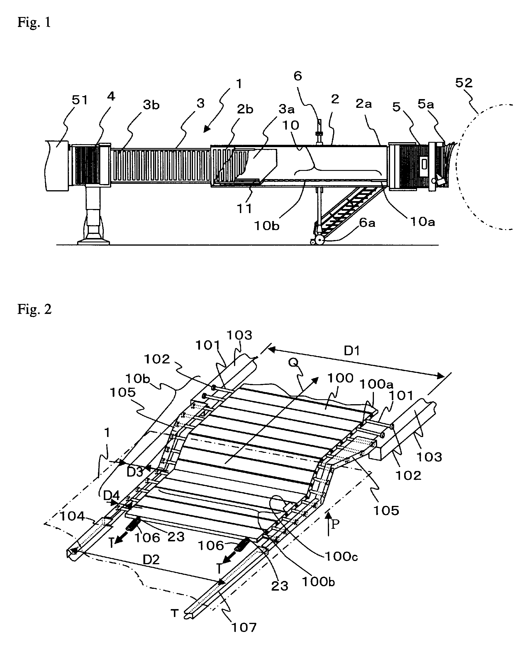
[0022]With reference to FIGS. 1 to 3, a most general PBB according to a first embodiment of the present invention is described. FIG. 1 is an external view illustrating a PBB 1 according to the present invention under a state in which the PBB 1 is extended to be connected to an aircraft, and illustrating an inside of an outer tunnel in cross section.

[0023]The PBB 1 includes an outer tunnel 2 and an inner tunnel 3. Each of the outer tunnel 2 and the inner tunnel 3 are each a hollow member having a passage on which passengers walk. The outer tunnel 2 has an outer shape larger than the cross section of the inner tunnel 3, and the inner tunnel 3 is inserted into the outer tunnel 2 from one end side thereof. The PBB 1 is capable of extending when the outer tunnel 2 and the inner tunnel 3 relatively move away from each other, or contracting when the outer tunnel 2 and the inner tunnel 3 relatively move closer to each other. The inner tunnel 3 is connected to a fixed bridge 51 of the airpor...

second embodiment

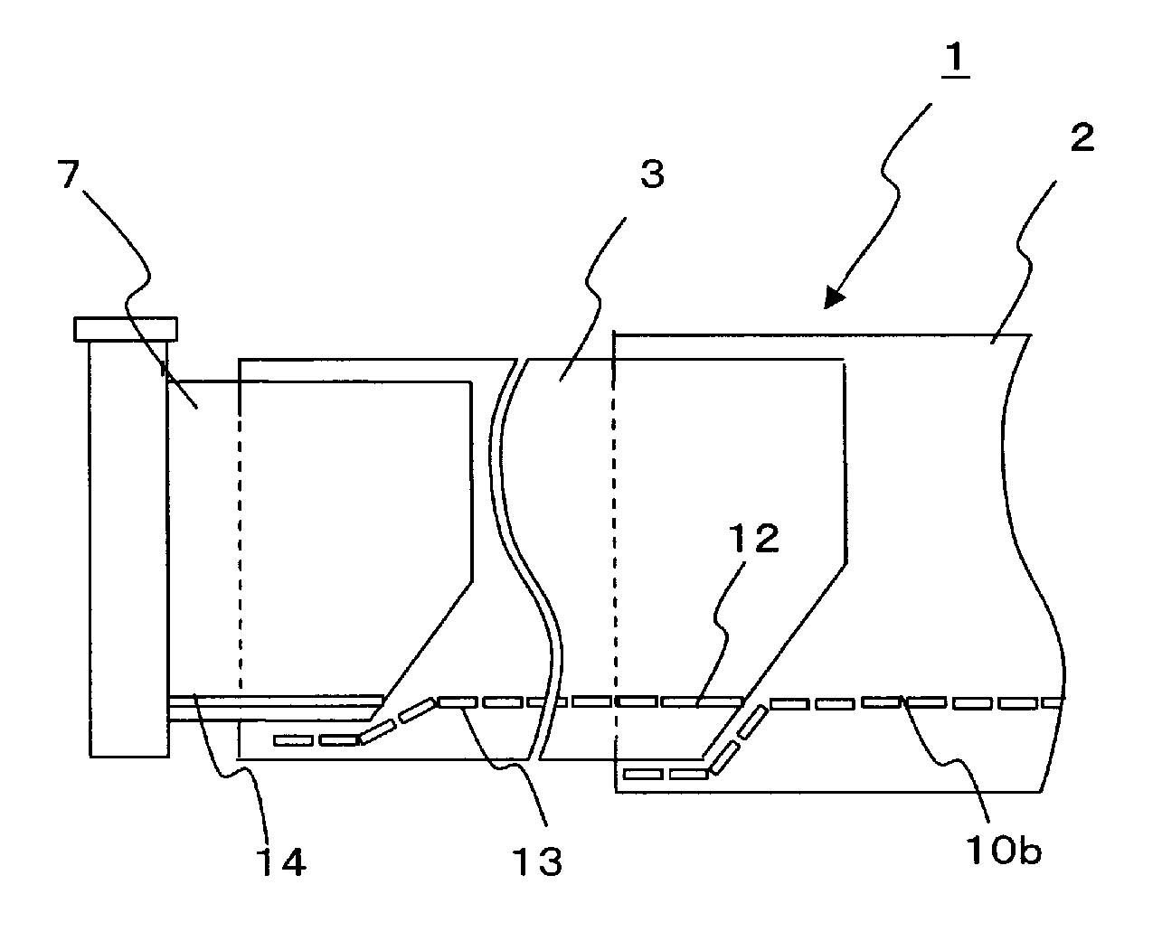
[0043]In the first embodiment, description is made of a case of the PBB including two tunnels consisting of the outer tunnel 2 and the inner tunnel 3. However, the present invention is also applicable to a PBB including three tunnels, in which a different third tunnel 7 connected to the airport building is inserted into the inner tunnel 3 (hereinafter referred to as “first tunnel”) which is inserted into the outer tunnel 2 (hereinafter referred to as “second tunnel”) which is joined to the cab. This case is described with reference to FIG. 9. FIG. 9 is a view illustrating a PBB 1 according to a second embodiment of the present invention. In this case, the first embodiment may be applied between the first tunnel 3 and the second tunnel 2, and between the third tunnel 7 and the first tunnel 3. Thus, although the movable passage is not arranged in the first tunnel 3 in the first embodiment, as a matter of course, the present invention encompasses the case where a movable passage 13 is ...


PUM


Abstract

The passenger boarding bridge includes a first tunnel including a first fixed passage on which a passenger walks; and a second tunnel including a second fixed passage on which the passenger walks, the first tunnel being inserted into the second tunnel from one end side of the second tunnel, the second tunnel having another end side connected to a cab, the second fixed passage being fixed to the another end side. The second tunnel includes a movable passage including multiple plate floor members in a chain manner, the movable passage having one end fixed to the second fixed passage of the second tunnel in a pivotable manner. Accordingly, a passenger boarding bridge in which a passage level difference is eliminated at a joint part between an inner tunnel and an outer tunnel can be realized.

Description

TECHNICAL FIELD[0001]The present invention relates to a passenger boarding bridge (hereinafter referred to as “PBB”) which is equipped in airports, for enabling passengers to board a passenger aircraft.BACKGROUND ART[0002]In a passenger aircraft (hereinafter referred to as “aircraft”), passengers board or disembark from (hereinafter referred to as “board and the like”) the aircraft through a doorway provided to an airframe. Between the doorway and a gate provided in the airport building, a PBB is installed. Normally, the PBB is stored in a contracted state when no passengers and the like are boarding. At the time of boarding and the like of the passengers on the aircraft, the PBB extends toward the doorway of the aircraft to connect to the doorway of the aircraft. The PBB is fixed after being substantially matched with the doorway of the aircraft, to thereby enable the passengers and the like to board and the like through the doorway.[0003]The PBB generally includes an inner tunnel ...

Claims


Application Information

Patent Timeline
Patent Type & Authority Patents(United States)
IPC IPC(8): E01D15/10B64F1/305
CPCB64F1/305E01D15/10
Inventor WADA, MASAFUMI
Owner ZENNIKKU MOTOR SERVICE
Why Eureka
Try Eureka