Light device with 3D effect for a motor vehicle

a technology of 3d effect and motor vehicles, applied in the field of light modules, can solve problems such as type approval difficulties, and achieve the effect of being particularly efficien

Active Publication Date: 2015-07-28
VALEO VISION SA
View PDF14 Cites 10 Cited by
  • Summary
  • Abstract
  • Description
  • Claims
  • Application Information

AI Technical Summary

Benefits of technology

[0012]According to an exemplary embodiment of the invention, a light source is arranged at one end of the guide. It may be, for example, one or more incandescent lamps or even one or more light-emitting diodes. A significant portion of the light rays emitted by the light source passes through the input face of the light guide, arranged facing the light source. The light-emitting diodes allow for a simpler embodiment of the device.
[0033]The features of the invention are advantageous in that they make it possible to produce a light module with depth effect, which is particularly efficient from a brightness and style viewpoint.

Problems solved by technology

From a photometric viewpoint, this means that a not-inconsiderable portion of the outer surface of the light does not participate in the signaling, which can in some cases lead to type-approval difficulties, notably for a “stop” function.

Method used


Image

  • Light device with 3D effect for a motor vehicle
  • Light device with 3D effect for a motor vehicle
  • Light device with 3D effect for a motor vehicle

Examples


Embodiment Construction

[0040]The exemplary embodiment of the invention illustrated in the figures is deliberately simplified and schematic in the interests of clarity of explanation of the invention. In practice, the various constituent elements of the invention will be able to take substantially more complex forms, notably because of the various dimensioning-related constraints.

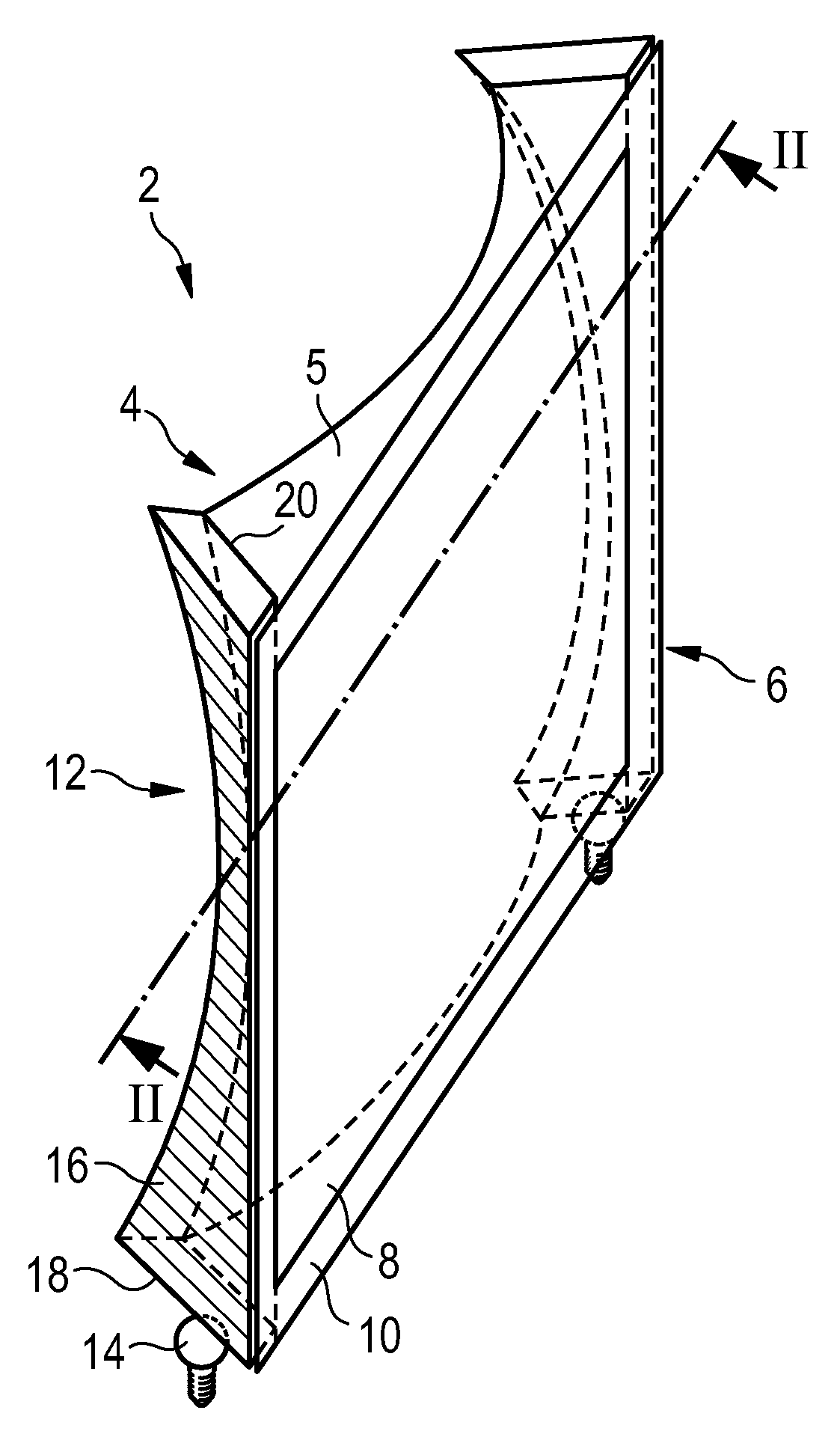
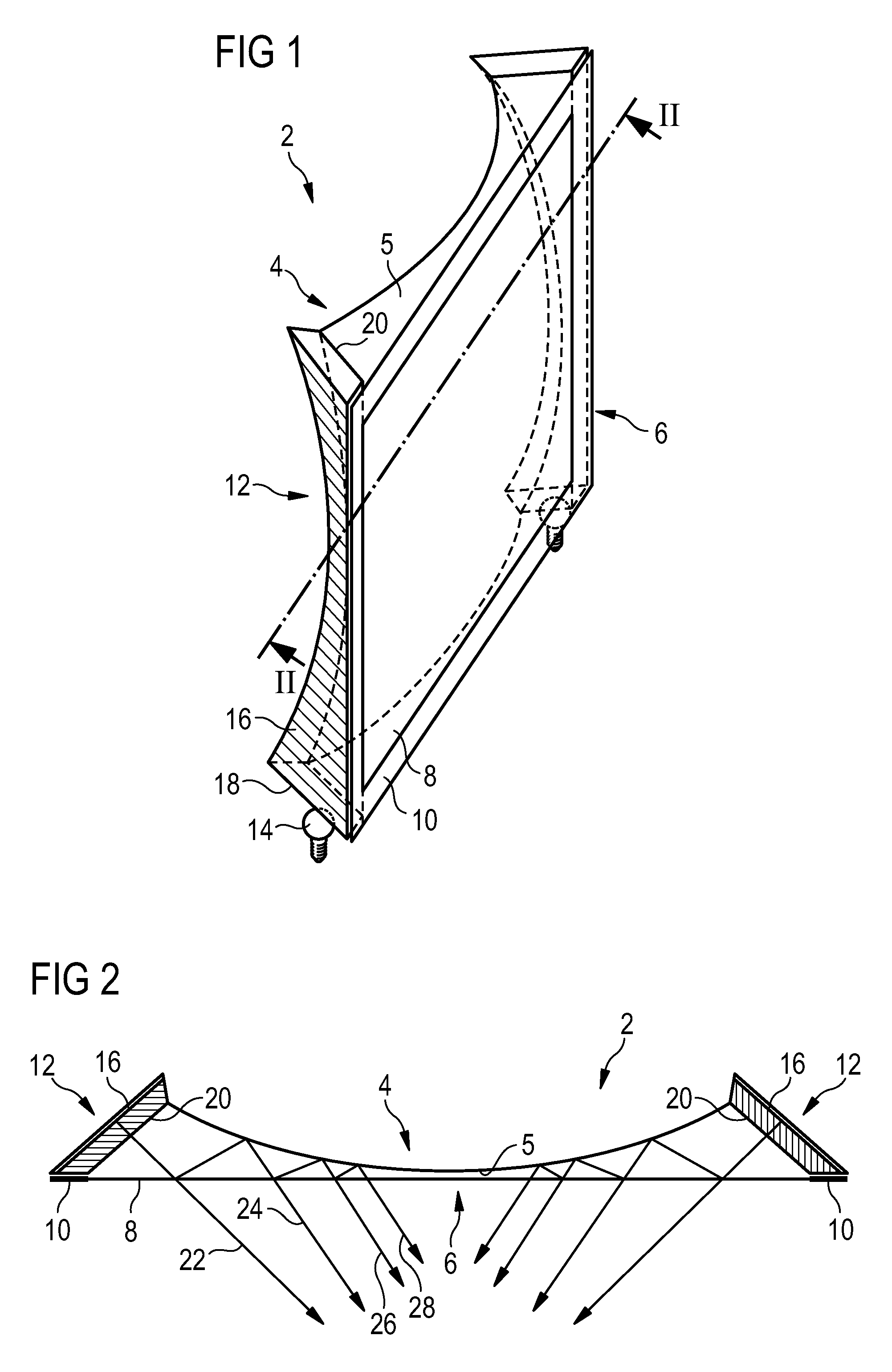
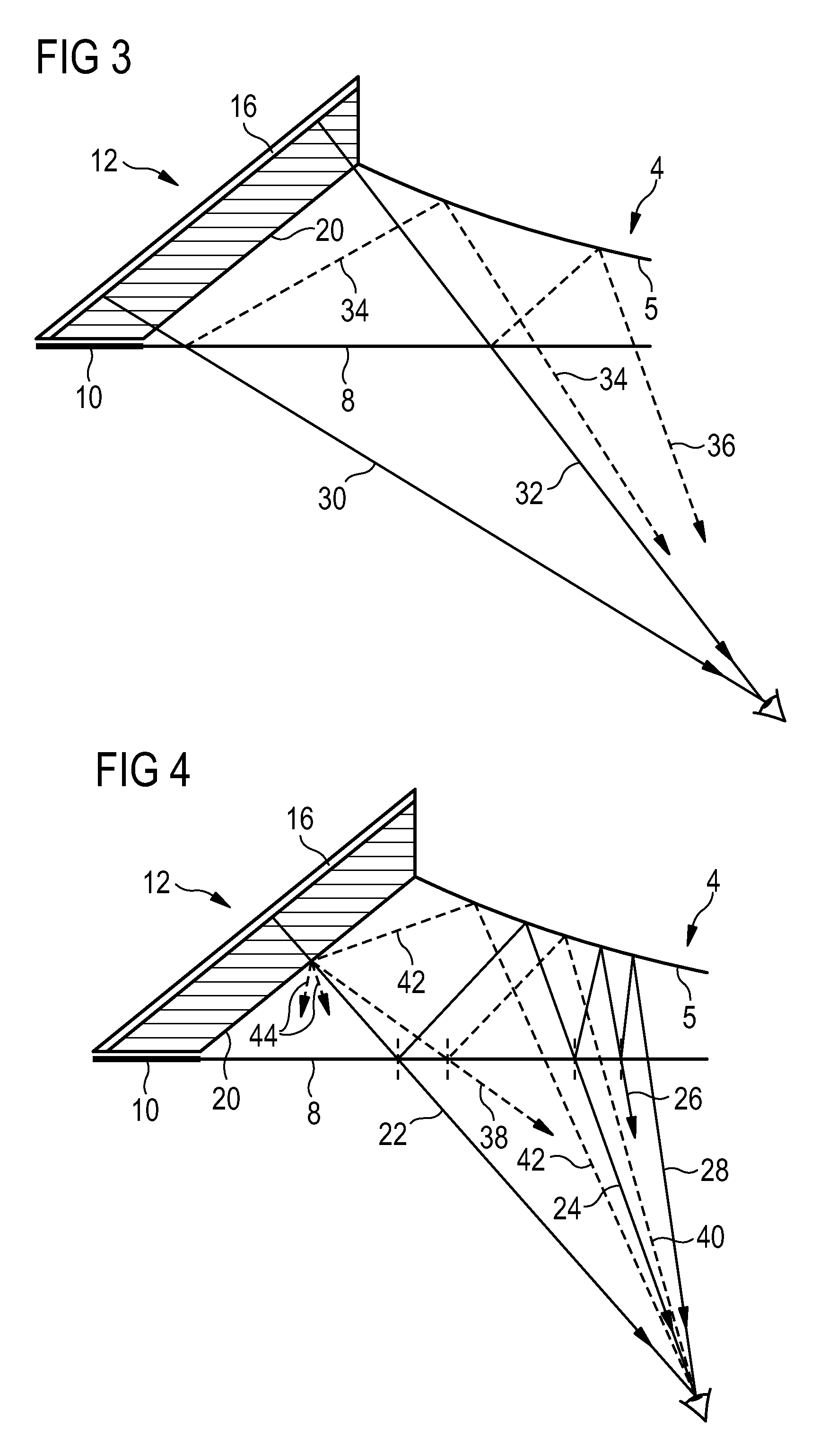
[0041]The light module 2 illustrated in FIG. 1 essentially comprises a reflector 4 with a reflecting surface 5 and a screen 6 extending facing the reflecting surface 5. The screen comprises a semi-reflecting area 8 surrounded by a mask 10. The screen is generally flat and the reflecting surface 5 is generally convex. The screen 6 and the reflector 4 form a quadrilateral in which two opposite edges are each provided with a light-emitting device 12. The latter extends longitudinally along the corresponding edges of or facing the semi-transparent area 8 and the reflecting surface 5. The light-emitting device 12 also extends transvers...


PUM


Abstract

The invention deals with a light module, notably for motor vehicles, comprising a reflector with a reflecting surface , a screen arranged facing the reflector, the screen a semi-reflecting area, and a light guide extending longitudinally along the screen and the reflector. The guide comprises a diffusing output face extending transversally from the semi-reflecting area of the screen to the reflector. A portion of the rays exiting from the output face passes through the semi-transparent area, the other portion being also reflected toward the reflecting surface to form successive images with a depth effect of 3D type, without dark areas between these images.

Description

CROSS-REFERENCE TO RELATED APPLICATIONS[0001]This application claims priority to French Application No. 1258900 filed Sep. 21, 2012.BACKGROUND OF THE INVENTION[0002]1. Field of the Invention[0003]The invention deals with a light module, notably for a motor vehicle. More particularly, the invention deals with an interior lighting module of the vehicle, such as a roof light or a side fixture, or even a signaling module of the “position” (or “side marker”) type and / or of the “stop” light type for vehicles. Even more particularly, the invention deals with a signaling device generating a depth effect in three dimensions by virtue of a particular optical device. The invention also deals with a signaling device comprising such a module.[0004]2. Description of the Related Art[0005]The patent document EP 1 916 471 A1, which is equivalent to U.S. Publication No. 2008 / 0094842, describes a rear light of the “side marker” type comprising a cavity formed by a reflector and a screen arranged at a ...

Claims


Application Information

Patent Timeline
Patent Type & Authority Patents(United States)
IPC IPC(8): F21S8/10B60Q3/00B60Q3/02G02B27/22F21W107/10
CPCB60Q3/0283F21S48/00F21S48/217F21S48/2237F21S48/2268F21S48/2287F21S48/24G02B27/2221G02B27/2235F21S48/23B60Q3/004B60Q3/64B60Q3/745F21S43/14F21S43/145F21S43/239F21S43/245F21S43/247F21S43/30F21S43/40G02B30/35G02B30/40
Inventor DUBOSC, CHRISTOPHETASSY, PIERRE LOUIS
Owner VALEO VISION SA
Why Eureka
Try Eureka