Plug unit and connection system for connecting capillary tubes, especially for high-performance liquid chromatography

a technology of capillary tubes and plug units, which is applied in the direction of couplings, components, instruments, etc., can solve the problems of unsatisfactory sealing position, unsatisfactory deformation, and unfavorable deformation

Active Publication Date: 2015-07-28
DIONEX SOFTRON
View PDF17 Cites 27 Cited by
  • Summary
  • Abstract
  • Description
  • Claims
  • Application Information

AI Technical Summary

Benefits of technology

[0022]According to another configuration of the invention, the plug capillary tube can have a second outer jacket layer or a jacket element at least in one axial sub-region that is surrounded by the pressure piece, or, in any case, in a sub-region in which a crimped connection is produced or is to be produced. This jacket layer can either be mounted rigidly onto the plug capillary tube, for example, through extrusion coating or by the pushing on or adhering of a sleeve made from a corresponding suitable material, or through galvanic application or deposition of metals. In this way, the outer diameter of the pressure piece can be easily adapted to the inner diameter of the capillary tube receptacle opening of the bushing unit, even if the wall of the pressure piece is to have a structure thin enough to permit subsequent crimping.
[0023]In addition, by selecting a sufficiently elastic material, it can be achieved that, in the case of plug capillary tubes that are made from a hard, nondeformable, and / or brittle material, radial forces that are high enough to cause destruction or damage are not exerted on the plug capillary tube at the position at which the pressure piece is crimped.

Problems solved by technology

Here, however, it is disadvantageous that the sealing position is not realized in the plane of the end surface perpendicular to the longitudinal axis of the capillary tube, but is instead offset rearward a certain distance from the end surface in the axial direction.
In this way, a dead volume is produced that has a disadvantageous effect, especially in high-performance liquid chromatography.
Such a deformation is undesired, especially because the sealing element here is connected to the capillary tube with a positive-fit and non-positive-fit connection, and the sealing element can no longer be easily shifted in the axial direction onto the capillary tube.
If the sealing connection is released and should such a plug element be screwed into another bushing unit, for example, because a component of the chromatography system must be replaced, then, indeed, a tight connection can be produced, but, due to tolerances or manufacture-dependent differences in the depth of the receptacle opening, it can no longer be guaranteed that the capillary tube applies a force again with its end surface on the end surface of the line to be connected.
If the receptacle opening of the bushing unit of the exchanged component is longer in the axial direction than the previously used component, then an undesired dead volume is created.
If the receptacle opening for the capillary tube in the exchanged component is shorter in the axial direction than the previously used component, then the capillary tube is even deformed, possibly damaged, by the pressure of the attachment screw, and a tight connection is no longer possible in certain circumstances.
However, in the case of such a fitting, a small dead volume also can be rarely avoided, if the end surfaces of the capillary tube and the line to be connected are directly opposite each other or contact each other, because the sealing position is not located in the region of the end surface of the capillary tube or the line to be connected.
Here, there is the risk again that the ferrule is “crimped tight” onto the capillary tube, especially when the sealing element is made from a metal, for example, stainless steel.
In addition, in this plug unit it is disadvantageous that a support element for the screw spring must be mounted on the capillary tube, wherein this support element makes the production of such a plug unit more complicated.
There is no flexibility with respect to the use of the unit for different depths of the capillary tube receptacle borehole.
In addition to the already mentioned disadvantages, the known connection systems feature the disadvantage that the risk arises that the sealing element remains in place in the relevant receptacle opening of the bushing unit when the plug unit is dismounted and the capillary tube is pulled out from the bushing unit.
However, this represents an additional expense and increases the dead volume of a connection.
In addition, in the case of an unfavorable tolerance position, an additional dead volume between the sleeve and capillary tube could also be created.

Method used


Image

  • Plug unit and connection system for connecting capillary tubes, especially for high-performance liquid chromatography
  • Plug unit and connection system for connecting capillary tubes, especially for high-performance liquid chromatography
  • Plug unit and connection system for connecting capillary tubes, especially for high-performance liquid chromatography

Examples


Embodiment Construction

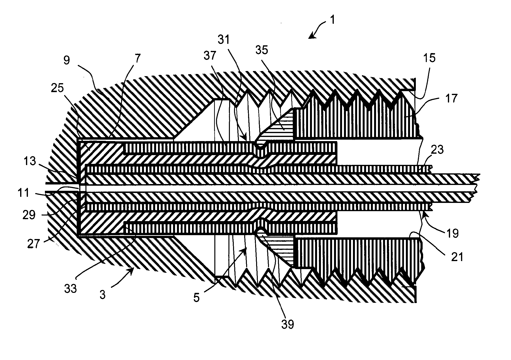
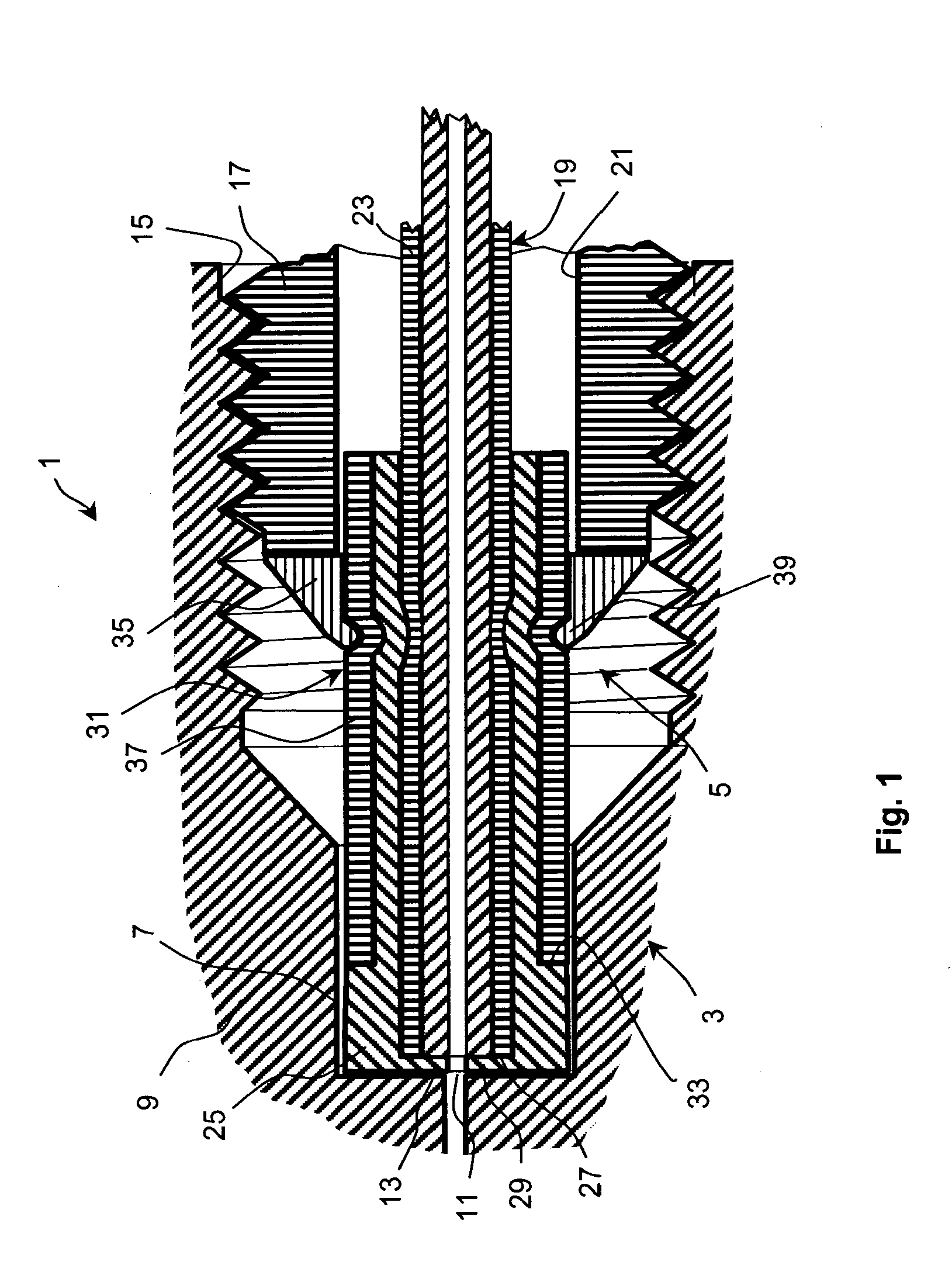
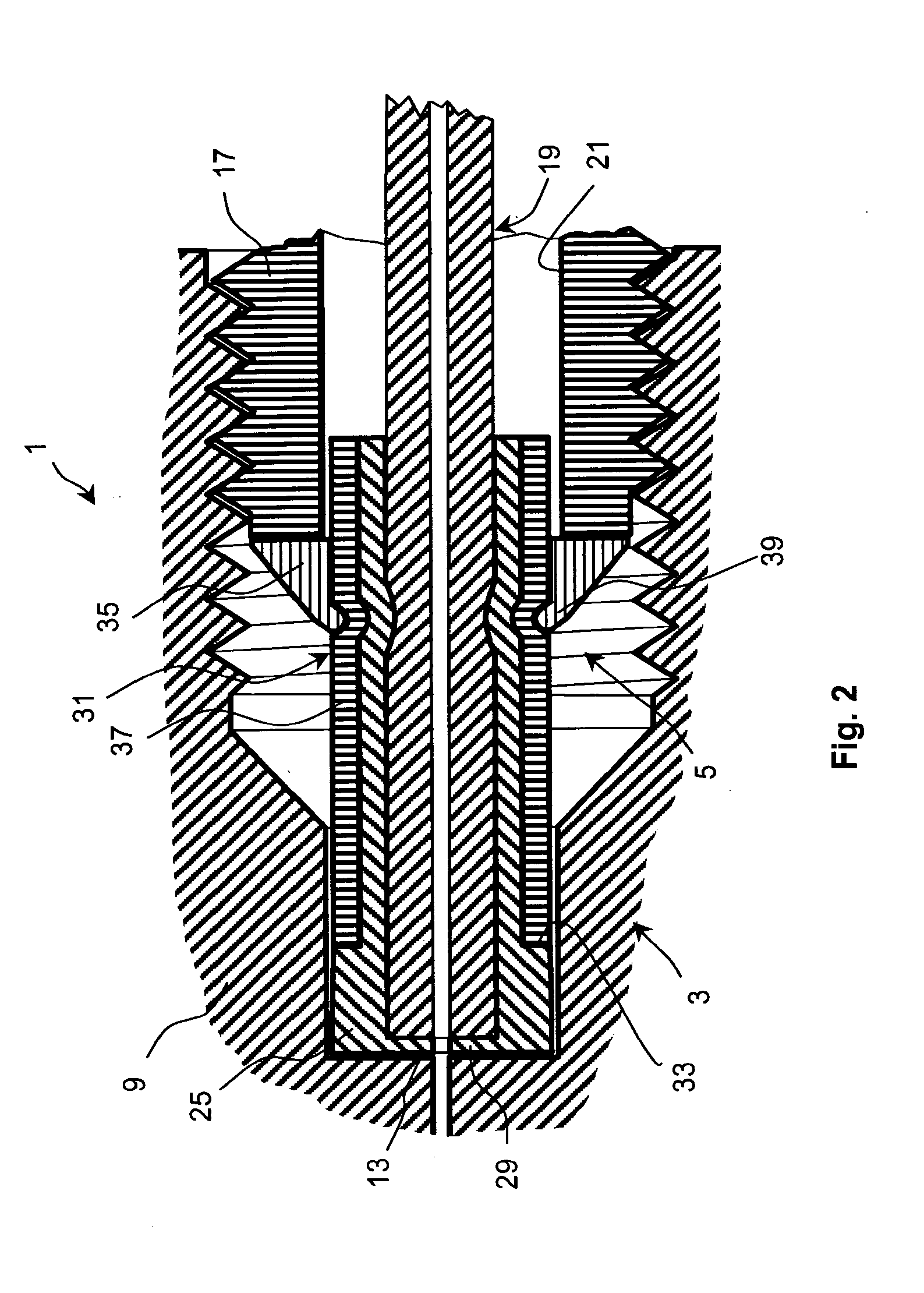
[0034]The connection system 1 shown in FIG. 1 in a longitudinal section for connecting capillary tubes, especially for high-performance liquid chromatography, comprises a bushing unit 3 and a plug unit 5. The bushing unit 3 is shown with only the part that is important for understanding the present invention, namely with the bushing housing 9 having the capillary tube receptacle opening 7. The bushing housing 9 can be mounted, for example, in a component of a chromatography device, for example, a chromatography column. The bushing housing 9 has a bushing capillary tube opening 11 that is constructed centrally in the floor wall 13 of the capillary tube receptacle opening 7. The capillary tube receptacle opening 7 expands into a receptacle opening 15 for a plug housing 17 of the plug unit 5. The receptacle opening 15 is here provided on its inner wall with a thread, for example, a fine thread that interacts with a corresponding thread or fine thread on the outer wall of the plug housi...


PUM

PropertyMeasurementUnit
pressuresaaaaaaaaaa
pressureaaaaaaaaaa
volumeaaaaaaaaaa

Abstract

A plug unit for connecting capillary tubes includes a plug housing that has an axial borehole, a plug capillary tube that projects through the axial borehole, and a sealing element that surrounds the plug capillary tube. The front end of the plug capillary tube is sealed by an elastic and/or plastic deformation of the sealing element against the capillary tube receptacle opening of a bushing unit. A hollow cylindrical pressure piece is provided that surrounds the sealing element in an axial region facing away from the end surface of the plug capillary tube, and the pressure piece has a rearward end side that faces away from the end surface of the plug capillary tube and that can be loaded by the plug housing with an axial pressure force when the plug unit and bushing unit are connected.

Description

TECHNICAL FIELD OF THE INVENTION[0001]The invention relates to a plug unit for connecting capillary tubes, especially for high-performance liquid chromatography. In addition, the invention relates to a connection system including a bushing unit and plug unit.BACKGROUND OF THE INVENTION[0002]In chromatography systems, liquids or gases are fed through suitable connection lines between the components of the relevant system. These connection lines, that can be made, for example, from stainless steel, have available at their ends suitable connection systems, also called fittings, in order to be able to create a tight connection with the connections of the components.[0003]Such a connection system was already described in 1975 in U.S. Pat. No. 3,880,452. A capillary tube forming the connection line between two components is here pushed into the capillary tube receptacle opening of a bushing unit or connection unit and fixed in the bushing by means of an attachment screw that has a central...

Claims


Application Information

Patent Timeline
Patent Type & Authority Patents(United States)
IPC IPC(8): F16L17/00G01N30/60
CPCG01N30/6026G01N2030/027F16L25/0018F16L37/02
Inventor HOCHGRAEBER, HERMANNSATZINGER, ADOLFBURGER, DANIELUNGER, ANDREAS
Owner DIONEX SOFTRON
Why Eureka
Try Eureka