Monitoring device for tyres for vehicle wheels, tyre for vehicle wheels provided with said monitoring device, and method for installing an electronic unit in said tyre

a technology for monitoring devices and tyres, which is applied in the direction of tyres, vehicle components, tyre measurements, etc., can solve the problems of fatigue and/or progressive wear of connecting parts, early breakage of connecting parts, and concentration of stresses and/or deformations, so as to improve reliability and durability, reduce stress concentration, and improve the effect of reliability and durability

Active Publication Date: 2015-08-04
PIRELLI TYRE SPA
View PDF35 Cites 3 Cited by
  • Summary
  • Abstract
  • Description
  • Claims
  • Application Information

AI Technical Summary

Benefits of technology

[0017]The Applicant perceived that controlling the mechanical interaction between the electronic unit and the connecting member, would have allowed to quite considerably reduce the concentration of the stresses on the connecting member, thus ensuring a reliable and enduring bond between the electronic unit and the tyre.
[0018]After lengthy experimentation, the Applicant found that leaving one or more gaps between the outer surface of the holding body of the electronic unit and the surface confining a cavity predisposed in the connecting member and adapted to house the electronic unit, would have allowed to significantly improve the reliability and durability of the bond between the electronic unit and the tyre by means of the connecting member.
[0019]Without being confined to any interpretive theory, the Applicant deems that such result can depend on the fact that the gap or the gaps between the surface of the cavity in which the electronic unit is housed and the surface of the electronic unit itself allows / allow the connecting member to be gradually shaped to the surface of the electronic unit in case of impact / interaction between the two surfaces, facilitating a particularly effective dissipation of the energy transmitted from the electronic unit to the connecting member even in case of strong deformations acting on the tyre; this limits the concentration of the stresses acting on the connecting member and the relative deformations and thus carries out a substantial damping and distribution action on a greater surface area of the impact itself.

Problems solved by technology

The Applicant has however found that due to the strong stresses to which the tyre is subjected during use, as well as to the coupling between an element brought to bend during rolling (the tyre) and a rigid element (the electronic unit), a connection of this kind can cause a concentration of stresses and / or deformations, and consequently a fatigue and / or progressive wear of the connecting member, in particular when the latter is associated with the inner surface of the tyre at a crown portion thereof (e.g. at the equatorial plane of the tyre).
The Applicant therefore observed that the concentration of stresses caused by the mechanical interference between the electronic unit and the walls of the cavity in which said electronic unit is housed can lead to a early breakage of the connecting member, and to a situation in which the electronic unit is no longer constrained to the inner surface of the tyre, but is moved without any control inside the same, with clear negative consequences both regarding the operation and the integrity of the electronic unit itself.

Method used


Image

  • Monitoring device for tyres for vehicle wheels, tyre for vehicle wheels provided with said monitoring device, and method for installing an electronic unit in said tyre
  • Monitoring device for tyres for vehicle wheels, tyre for vehicle wheels provided with said monitoring device, and method for installing an electronic unit in said tyre
  • Monitoring device for tyres for vehicle wheels, tyre for vehicle wheels provided with said monitoring device, and method for installing an electronic unit in said tyre

Examples


Embodiment Construction

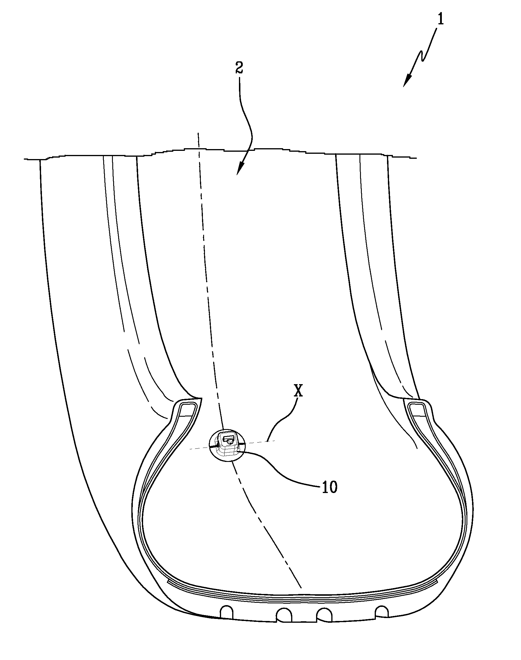
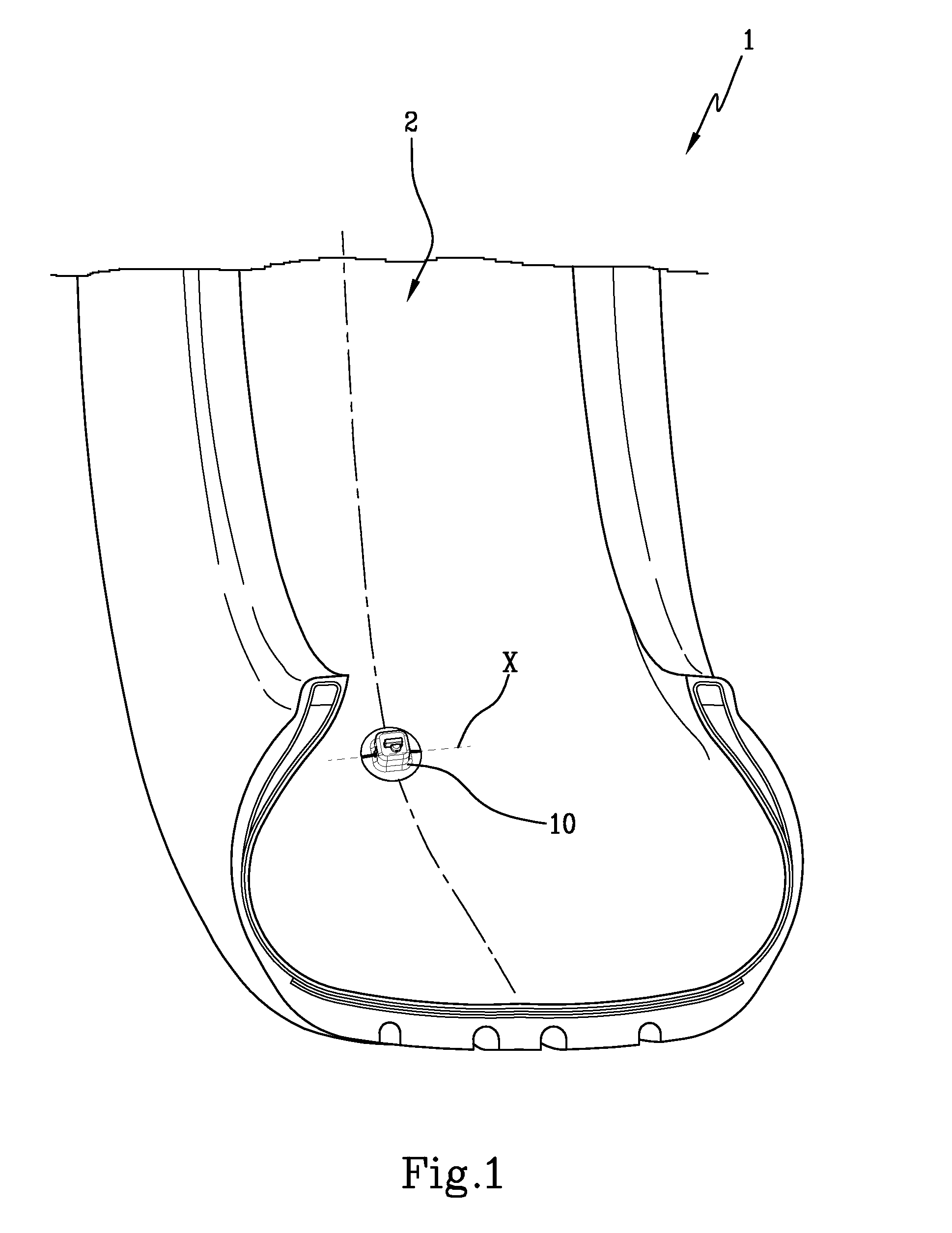
[0088]With reference to the attached figures, a tyre for vehicle wheels provided with a monitoring device according to the present invention is indicated in its entirety with 1. The monitoring device is indicated with the reference number 10.

[0089]The tyre 1, per se known, is not described herein in detail.

[0090]The tyre 1 (FIG. 1) comprises an inner surface 2, preferably comprising or constituted by the so-called “liner”.

[0091]The monitoring device 10 is mounted on such inner surface 2.

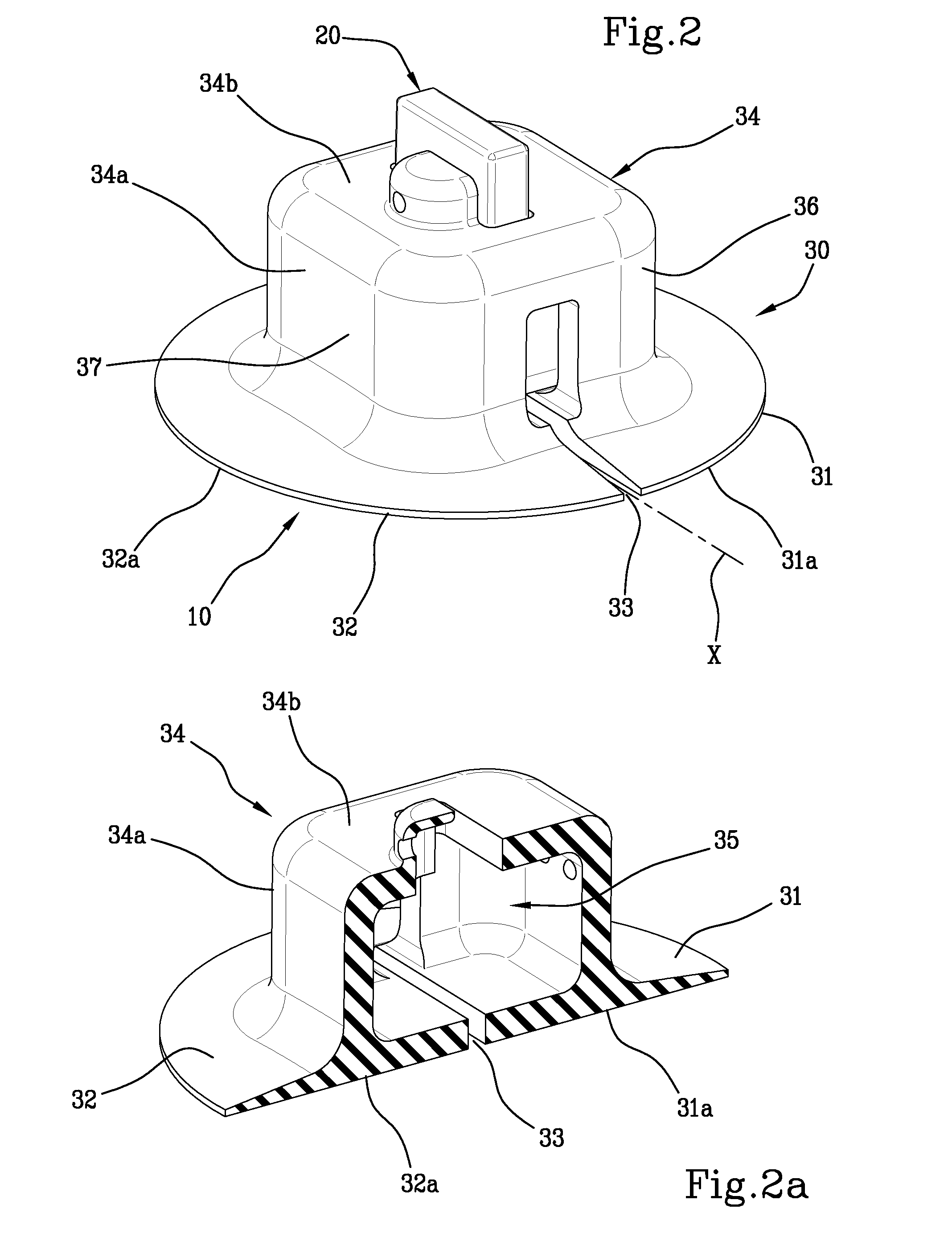
[0092]The monitoring device 10 comprises an electronic unit 20 (FIGS. 4-5).

[0093]Preferably the electronic unit 20 comprises at least one sensor 21 and at least one antenna 22.

[0094]For example, said sensor 21 is a pressure and / or temperature sensor, configured for detecting a pressure and / or a temperature inside the tyre 1.

[0095]In a further embodiment, the sensor 21 can be a sensor of accelerometer type, configured for detecting mechanical stresses to which the tyre 1 is subjected.

[0096]In addition...


PUM

PropertyMeasurementUnit
widthaaaaaaaaaa
widthaaaaaaaaaa
frequencyaaaaaaaaaa

Abstract

A monitoring device for tires for vehicle wheels includes: an electronic unit; a connecting member configured for constraining the electronic unit to a tire, the connecting member including: a first and a second base portion, mutually separated by a separated region, each of the base portions having a respective base surface associable with an inner surface of a tire; a housing portion associated with the base portions defining, in cooperation with said base portions, a cavity for housing the electronic unit, wherein the housing portion includes at least one side structure, configured for exerting a containing action at least relative to movements of the electronic unit carried out in a major extension direction of the separation region and with respect to movements of said electronic unit carried out in a direction orthogonal to the major extension direction of the separation region wherein the cavity is confined at least by a side surface defined by an inner surface of the side structure, wherein the electronic unit includes at least one sensor, at least one antenna and a holding body for housing at least the sensor and the antenna, wherein the holding body has at least one side surface, wherein, when the electronic unit is inserted in the cavity: the side surface of the holding body faces the side surface of the cavity, and the sizes of said cavity and of the holding body are such as to form at least one first gap at least partly separating the side surface of the holding body and the side surface of the cavity.

Description

CROSS REFERENCE TO RELATED APPLICATIONS[0001]This application is a national phase application based on PCT / IB2012 / 057411, filed Dec. 18, 2012, which claims the priority of Italian Application No. MI2011A002427, filed Dec. 29, 2011, and the benefit of U.S. Provisional Application No. 61 / 594,071, filed Feb. 2, 2012, the content of each application being incorporated herein by reference.BACKGROUND OF THE INVENTION[0002]1. Field of the Invention[0003]The present invention regards a monitoring device for tyres for vehicle wheels.[0004]The present invention also regards a tyre for vehicle wheels provided with said monitoring device.[0005]The present invention also regards a method for installing an electronic unit in a tyre.[0006]2. Description of the Related Art[0007]The need to monitor, in real time, the operating conditions of tyres, and possibly keep track of the time evolution of parameters representative of such operation, has assumed increasing importance by virtue of the requireme...

Claims


Application Information

Patent Timeline
Patent Type & Authority Patents(United States)
IPC IPC(8): G01M17/02B60C23/02B60C23/04B29D30/00
CPCB60C23/0493B60C23/0408B29D2030/0077Y10T29/49492
Inventor BRUSAROSCO, MASSIMOMANCOSU, FEDERICOCOVOLO, FABIO
Owner PIRELLI TYRE SPA
Why Eureka
Try Eureka