Touch sensing device

a touch sensing device and touch technology, applied in the field of touch sensing devices, can solve the problems of high manufacturing cost inability to effectively reduce the size of inability to flexibly adjust the touch sensing operation performed by the touch sensing device based on extrinsic practicality

Active Publication Date: 2015-08-04
NUVOTON
View PDF13 Cites 0 Cited by
  • Summary
  • Abstract
  • Description
  • Claims
  • Application Information

AI Technical Summary

Benefits of technology

[0059]For the aforementioned embodiments compared to prior art, the embodiments in the present disclosure can be applied such that only a few capacitors are necessary to achieve quite sensitive touch sensing operations and to save the capacitors, to further reduce the circuit layout area occupied by the capacitors, such that the size of the touch sensing device 300 can be significantly reduced and the manufacturing cost can be decreased as well. Moreover, in the condition that the maximum equivalent capacitance is fixed, the sensitivity of the touch sensing device itself can be modified by variations of the driving signal, such that the touch sensing operation performed by the touch sensing device can be flexibly adjusted based on extrinsic practical situations or user's conditions.
[0017]In the following description, specific details are presented to provide a thorough understanding of the embodiments of the present disclosure. Persons of ordinary skill in the art will recognize, however, that the present disclosure can be practiced without one or more of the specific details, or in combination with other components. Weil-known implementations or operations are not shown or described in detail to avoid obscuring aspects of various embodiments of the present disclosure.

Problems solved by technology

However, for example in a capacitive touch sensing device, many capacitors are usually required for performing a touch sensing operation, and a circuit layout area occupied by these capacitors is significantly large, such that the size of the touch sensing device cannot be effectively reduced and the high manufacturing cost for the touch sensing device is also necessary.
Moreover, in a conventional touch sensing device, once the circuit layout of the capacitors is set, the sensitivity of the touch sensing device itself is also fixed accordingly and cannot be changed, such that the touch sensing operation performed by the touch sensing device cannot be flexibly adjusted based on extrinsic practical situations or user's conditions.
In conclusion, typical touch sensing devices all have the problem of having a too large circuit layout area occupied by these capacitors and the problem of being unable to be flexibly adjusted according to practical needs.

Method used


Image

  • Touch sensing device
  • Touch sensing device
  • Touch sensing device

Examples


first embodiment

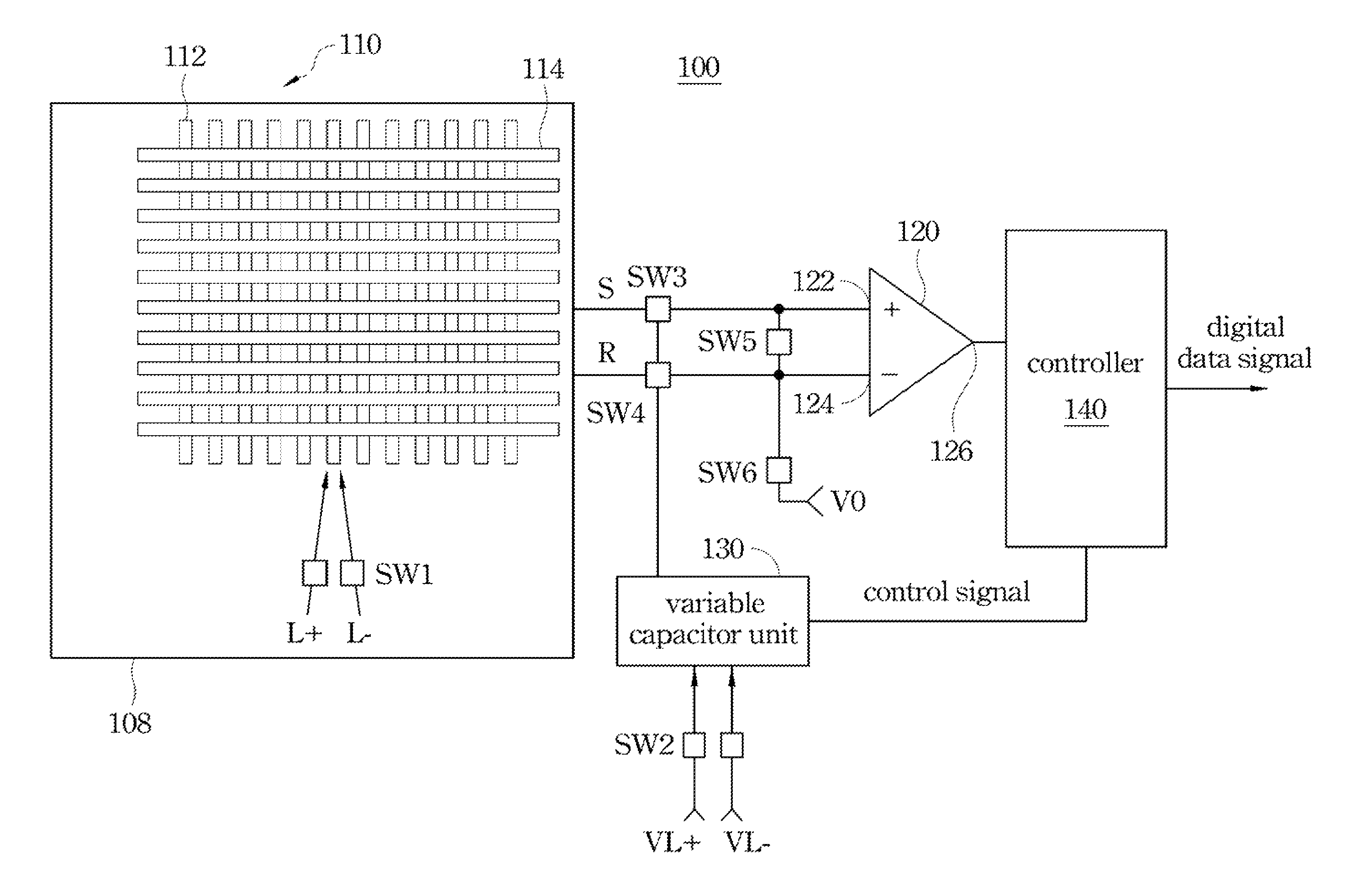
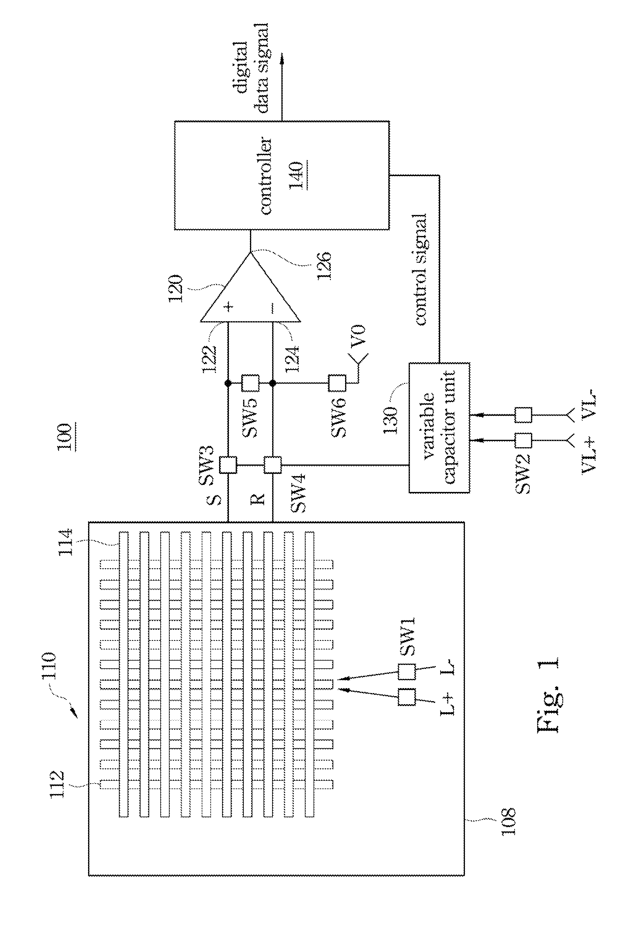
[0025]FIG. 1 is a schematic diagram of a touch sensing device according to the present disclosure. As shown in FIG. 1, the touch sensing device 100 includes a touch sensing trace layout 110, a comparator 120 and a variable capacitor unit 130. The touch sensing trace layout 110 is configured for performing a sensing operation according to at least one first driving signal e.g., driving signal L+ shown in FIG. 1) in a sensing state, such that the touch sensing trace layout 110 outputs one or more sensing signals corresponding to a touch event (e.g., the touch sensing trace layout 110 is touched by finger, stylus pen, etc.). The comparator 120 includes a first comparator input 122, a second comparator input 124, and a comparator output 126, in which the first comparator input 122 and the second comparator input 124 may be electrically coupled to the touch sensing trace layout 110 respectively through a path S and a path R, for receiving the sensing signals outputted by the touch sensin...

second embodiment

[0046]FIG. 3 is a schematic diagram of a touch sensing device according to the present disclosure. As shown in FIG. 3, the touch sensing device 300 includes a touch sensing trace layout 310, a comparator 320 and a variable capacitor unit 330. The touch sensing trace layout 310 is configured for performing a sensing operation according to at least one first driving signal (e.g., the driving signal L+) in a sensing state, such that the touch sensing trace layout 310 outputs one or more sensing signals corresponding to a touch event (e.g., the touch sensing trace layout 310 is touched by finger, stylus pen, etc.). The comparator 320 includes a first comparator input 322, a second comparator input 324, and a comparator output 326, in which the first comparator input 322 is electrically coupled through the path S to the touch sensing trace layout 310 and configured for receiving the sensing signal outputted by the touch sensing trace layout 310, and the second comparator input 324 is ele...


PUM


Abstract

A touch sensing device includes a touch sensing trace layout, a comparator and a variable capacitor unit. The touch sensing trace layout performs a sensing operation according to at least one first driving signal in a sensing state. An input of the comparator is electrically coupled to the touch sensing trace layout for receiving a sensing signal outputted by the touch sensing trace layout. The variable capacitor unit is selectively coupled to one of the inputs of the comparator, for correspondingly performing potential compensation to the sensing signal received by the input of the comparator according to at least one second driving signal.

Description

RELATED APPLICATIONS[0001]This application claims priority to Provisional Application Ser. No. 61 / 583,613 filed on Jan. 6, 2012 and Taiwan Patent Application Serial Number 101117418, filed May 16, 2012, which are herein incorporated by reference.BACKGROUND[0002]1. Technical Field[0003]The present disclosure relates to a sensing device. More particularly, the present disclosure relates to a touch sensing device.[0004]2. Description of Related Art[0005]For high technology nowadays, user interfaces of more and more electronic products have already employed touch panels, such that demands for touch sensing devices have increasingly matured. Touch sensing devices have already become the basis of any kind of user interface, and replacing traditional keyboard interface with touch sensing interface undoubtedly makes the user interface become more intuitional and easier for use.[0006]Moreover, one of ordinary skill in the art can use the touch sensing interface to substitute mechanical keys ...

Claims


Application Information

Patent Timeline
Patent Type & Authority Patents(United States)
IPC IPC(8): G06F3/044
CPCG06F3/044G06F3/0445G06F3/0446
Inventor WANG, CHENG-CHIH
Owner NUVOTON
Why Eureka
Try Eureka