
Magnetic sensor having optimal free layer back edge shape and extended pinned layer

a magnetic sensor and free layer technology, applied in the field of magnetic data recording, can solve the problems of strength of pinned layer pinning and suffer, and achieve the effect of optimizing sensor free sensor performance and pinned layer stability, reducing sensor performance (mr ratio) and improving pinning strength

Active Publication Date: 2015-08-04
WESTERN DIGITAL TECH INC
View PDF24 Cites 11 Cited by
  • Summary
  • Abstract
  • Description
  • Claims
  • Application Information

AI Technical Summary

Benefits of technology

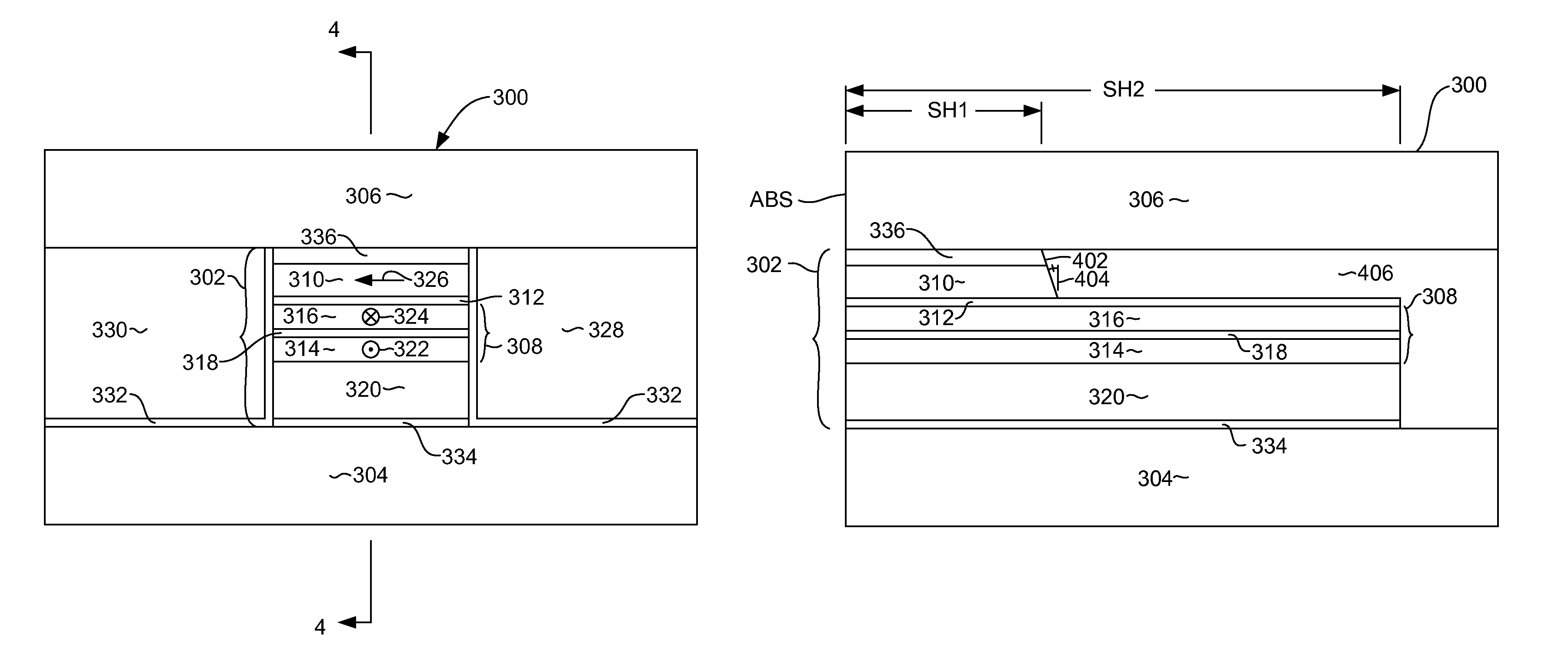
The patent text explains that by making the back edge of a sensor's free layer with an angle between 6 and 10 degrees, the performance of the sensor is optimized and its stability is improved. If the angle is too small, the pinned layer may be damaged, and if the angle is too big, the sensor's performance suffers. By keeping the angle at 6-10 degrees, the sensor achieves both optimal performance and robustness.

Problems solved by technology

If the back edge angle is less than 6 degrees the pinned layer may be damaged by the ion milling used to form the free layer back edge, and the strength of pinning of the magnetization of the pinned layer can suffer.

Method used


Image

  • Magnetic sensor having optimal free layer back edge shape and extended pinned layer
  • Magnetic sensor having optimal free layer back edge shape and extended pinned layer
  • Magnetic sensor having optimal free layer back edge shape and extended pinned layer

Examples


Embodiment Construction

[0018]The following description is of the best embodiments presently contemplated for carrying out this invention. This description is made for the purpose of illustrating the general principles of this invention and is not meant to limit the inventive concepts claimed herein.

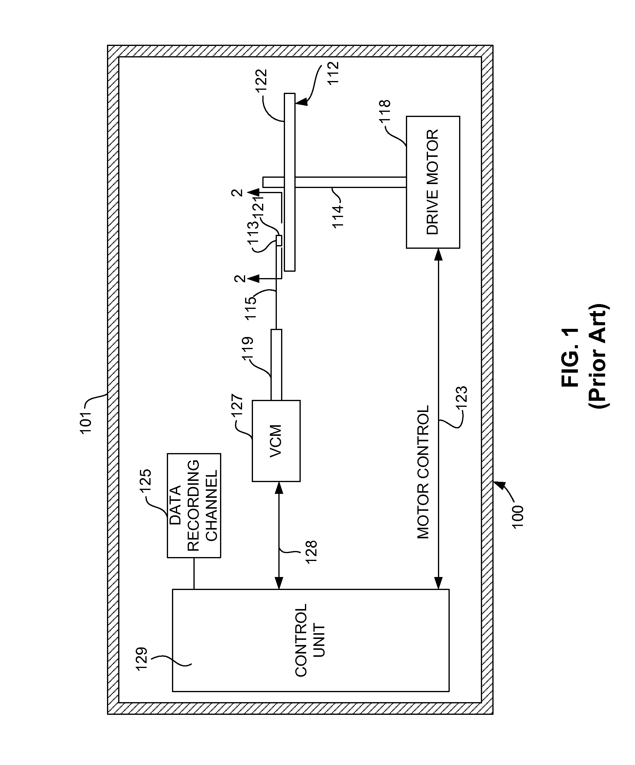
[0019]Referring now to FIG. 1, there is shown a disk drive 100 embodying this invention. The disk drive 100 includes a housing 101. At least one rotatable magnetic disk 112 is supported on a spindle 114 and rotated by a disk drive motor 118. The magnetic recording on each disk is in the form of annular patterns of concentric data tracks (not shown) on the magnetic disk 112.

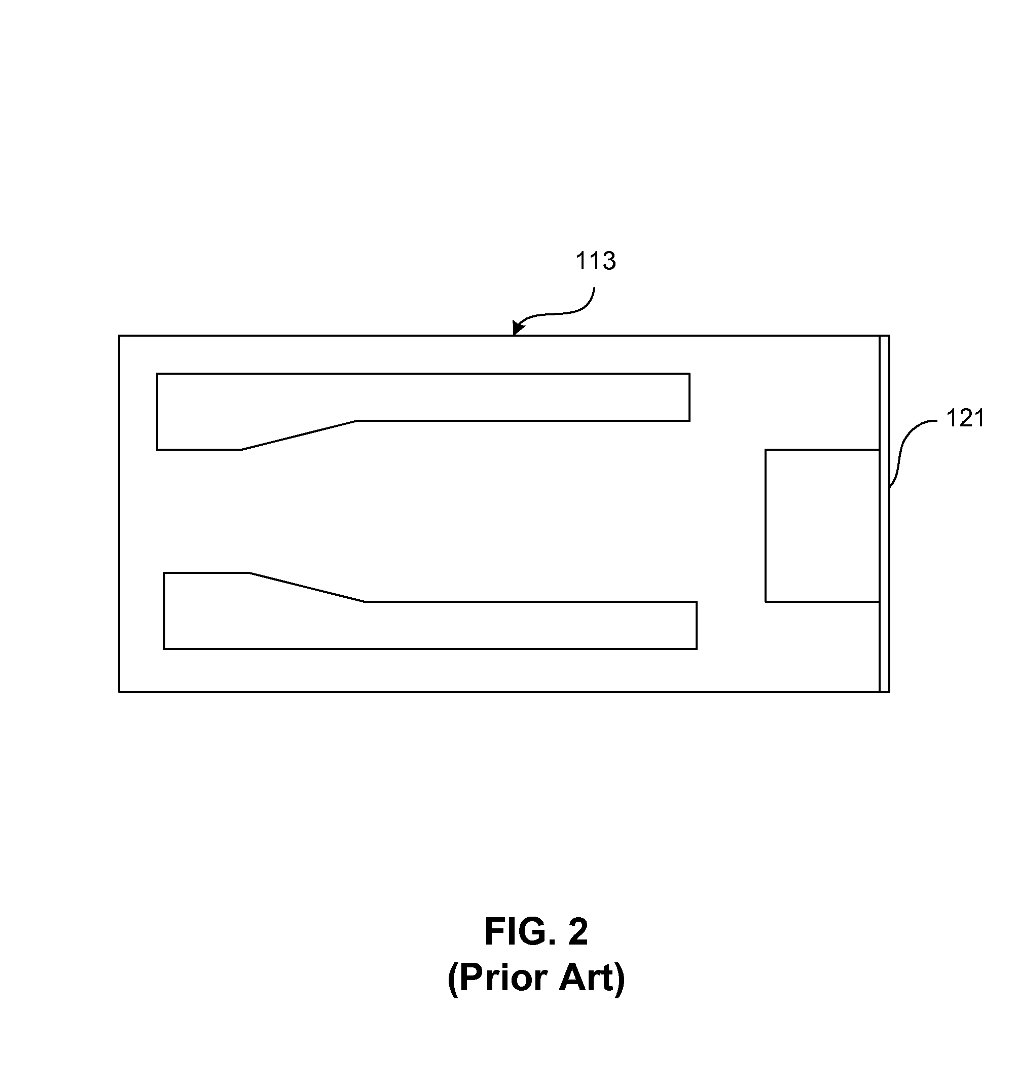
[0020]At least one slider 113 is positioned near the magnetic disk 112, each slider 113 supporting one or more magnetic head assemblies 121. As the magnetic disk rotates, slider 113 moves in and out over the disk surface 122 so that the magnetic head assembly 121 can access different tracks of the magnetic disk where desired data are written....


PUM

PropertyMeasurementUnit
angleaaaaaaaaaa
back edge angleaaaaaaaaaa
angleaaaaaaaaaa

Abstract

A magnetic read sensor having an extended pinned layer and having a free layer structure with a back edge formed at an angle for optimizing sensor performance and pinned layer pinning. The magnetic free layer has a back edge that is formed at an angle of between 6 and 10 degrees relative to a plane parallel with the air bearing surface plane. The magnetic sensor can be formed by forming the free layer stripe height with an ion milling that is performed at an angle of 6 to 10 degrees relative to normal.

Description

FIELD OF THE INVENTION[0001]The present invention relates to magnetic data recording and more particularly to a magnetic read head having an extended pinned layer structure and a free layer having a back edge formed at an angle for optimized sensor performance and stability.BACKGROUND OF THE INVENTION[0002]In recent years, as information technology has developed, interest has focused on the greater processing speeds of central processing units (CPU), as well as the increase in storage capacity of storage devices. Among these developments, magnetic disk storage devices are most often used as large capacity storage devices, and research is being performed into further increases in their speed and data density.[0003]Magnetic read heads that use magnetoresistive (MR) effect elements are used for reading the information on the magnetic disks of magnetic disk storage devices. Magnetoresistive effect elements normally have a structure in which an antiferromagnetic layer, a pinned layer, a ...

Claims


Application Information

Patent Timeline
Patent Type & Authority Patents(United States)
IPC IPC(8): G11B5/39
CPCG11B5/3909G11B5/398G11B5/3929G11B5/6082G11B2005/3996
Inventor WAGATSUMA, TAKASHIOKADA, YUKIMASAHOSHINO, KATSUMIKATAOKA, KOUJI
Owner WESTERN DIGITAL TECH INC
Learn More