
Oil premix burner

a technology of oil premix burner and oil premix, which is applied in the direction of burners, indirect carbon-dioxide mitigation, combustion types, etc., can solve the problems of relatively large overall combustion chamber compared to known designs, difficult heating of air, etc., and achieves the effect of improving combustion quality and robustness, improving the energy balance of the burner, and increasing the burner surfa

Inactive Publication Date: 2013-12-26
ROBERT BOSCH GMBH
View PDF3 Cites 4 Cited by
  • Summary
  • Abstract
  • Description
  • Claims
  • Application Information

AI Technical Summary

Benefits of technology

The present invention relates to a method for improving the quality and robustness of oil premix burners. It aims to optimize combustion quality and modulation capability. One important aspect is the use of an air heat exchanger that allows for a minimum temperature of combustion air at all operating points. The invention also includes a swirl-generating device that adjusts to the spray behavior of the oil injection device, resulting in a more complete mixing of oil mists and combustion air. This design ensures high-quality combustion and efficient energy utilization. Additionally, the invention addresses issues related to pressure loss and scalability in the supply path of the combustion air. Overall, this method enhances the performance and reliability of oil premix burners.

Problems solved by technology

Generally, the heating of air is relatively difficult because of its low heat capacity, because to do it, either an effective heat transition via a wall to the air flow and / or high wall temperatures are required.
Since, for the mixing and the combustion reaction, a certain minimum combustion element diameter is required, this design may lead, however, to an overall relatively large combustion chamber compared to known designs.

Method used


Image

  • Oil premix burner
  • Oil premix burner
  • Oil premix burner

Examples


Embodiment Construction

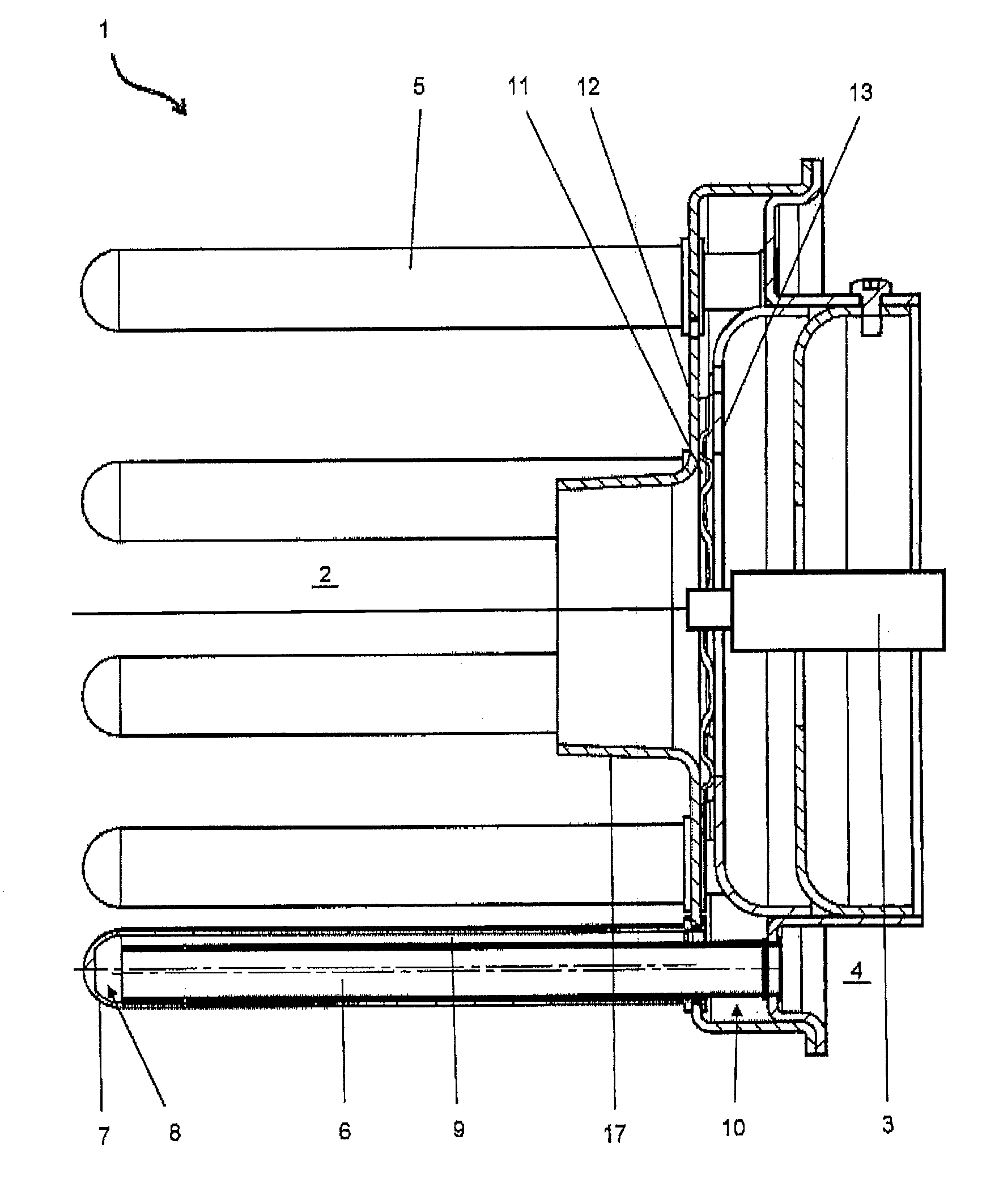
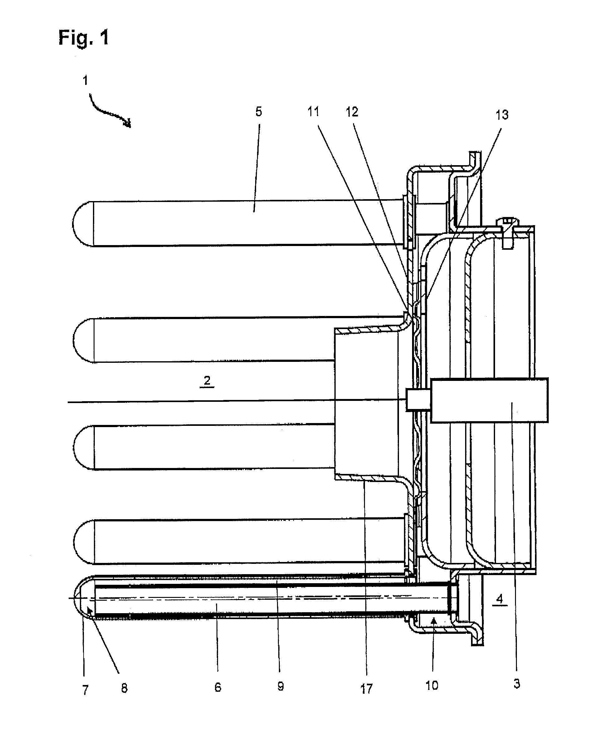
[0027]The oil premix burner is made up essentially of a combustion element 1, having a burner surface (not shown) on the outer lateral surface, a distribution chamber 2 below the burner surface, a central oil injection device 3, a combustion air channel 4 connected to a blower situated upstream as well as an air heat exchanger for the preheating of the combustion air in the area of the burner surface. The latter is made up of a plurality of double tube elements 5 that are distributed over the circumference, that extend with their axes parallel to combustion element 1 and have parallel flows through them, and having an inner tube 6 and an outer tube 7 having flows through them in series. In this context, each double tube element 5 is connected with the entry side of inner tube 6 to combustion air channel 4. The combustion air, in each case, in a turnaround zone 8 at the end face of the free end gets into annular space 9 that is formed between inner tube 6 and outer tube 7, and flows ...


PUM


Abstract

An oil premix burner comprising: a combustion element; a burner surface on the outer lateral surface; a distribution chamber below the burner surface; a central oil injection device; a combustion air channel connected to a blower situated upstream as well as an air heat exchanger for the preheating of the combustion air in the area of the burner surface. In each case, the annular space formed between the inner tube and the outer tube of all the double tube elements opens out into an annular-shaped collecting chamber, and the preheated combustion air, starting from the collecting chamber, flows inwards via a swirl-generating device into the area around the oil injection device into the distribution chamber.

Description

BACKGROUND OF THE INVENTION[0001]1. Field of the Invention[0002]The present invention relates to an oil premix burner having a combustion element.[0003]2. Description of the Related Art[0004]Such oil premix burners have a cylindrical combustion element having a burner surface on the outer lateral surface. Round about a central oil injection device there is a distribution chamber, as a rule, for the oil mist being created, so that the latter uniformly reaches the burner surface from within. The combustion air gets into the distribution chamber via at least one inflow opening in the vicinity of the oil injection device, which may be an injection valve or an oil nozzle which is fastened to a nozzle holder having an oil preheater. Upstream of the oil injection device there is a combustion air channel having a connection to a blower.[0005]In the case of gas burners, in particular, which are operated in a modulating manner, that is, in which the performance range is able to be controlled ...

Claims


Application Information

Patent Timeline
IPC IPC(8): F23D11/10F23D11/44F23D11/00
CPCF23D11/107F23D11/001F23D11/44F23L15/04F23C7/004F23D11/406Y02E20/34
Inventor MEDEIROS, ANTONIOLANG, RAPHAELRAUSCH, RAINERGESCHWEND, THOMASCECEN, SADIKRIPPLINGER, HANS-JOACHIMSCHROEDER, THORSTENHETCHE, JUERGEN
Owner ROBERT BOSCH GMBH
Learn More