Integrated surgical bleeding control system

a control system and surgical technology, applied in the field of integrated surgical bleeding control system, can solve the problems of difficulty in effective loading of patches with clotting factor, loss of surgical site, etc., and achieve the effect of simplifying the process of selecting and using a bleeding factor

Inactive Publication Date: 2015-08-11
LIGHT KENNETH DR
View PDF8 Cites 4 Cited by
  • Summary
  • Abstract
  • Description
  • Claims
  • Application Information

AI Technical Summary

Benefits of technology

[0005]With this invention, an overall system is provided which effectively prepares and accounts for bleeding control pads in a variety of different ways. In particular, each pad is provided with a small (e.g. one centimeter square) piece of flexible material, typically a gel foam material which can be to some extent absorbent to hold a clotting agent (such as Thrombin or a Thrombin / saline solution thereon). The pad also has a gauze portion which optionally, but preferably, has a radiopaque marker included thereon so that the patches can be prominently seen when the body of the patient is viewed through a fluoroscope or similar imaging equipment.
[0010]Accordingly, a primary object of the present invention is to provide a tray for assisting in the wetting of bleeding control pads with bleeding control agent for use in a surgical procedure.
[0012]Another object of the present invention is to provide a system for efficiently wetting bleeding control pads with the bleeding control agent for use in a surgical procedure.
[0014]Another object of the present invention is to provide a tray which uniformly wets pads with bleeding control agent to simplify the process of selecting and using a bleeding control pad during surgery.

Problems solved by technology

Such bleeding control patches are known to have a tab thereon as the patch itself can be rather small and there is a potential for it becoming lost in the surgical site.
Still, difficulty is encountered in loading the patches effectively with clotting factor, and accounting for the patches before, during and at close of a surgical procedure.

Method used


Image

  • Integrated surgical bleeding control system
  • Integrated surgical bleeding control system
  • Integrated surgical bleeding control system

Examples


Embodiment Construction

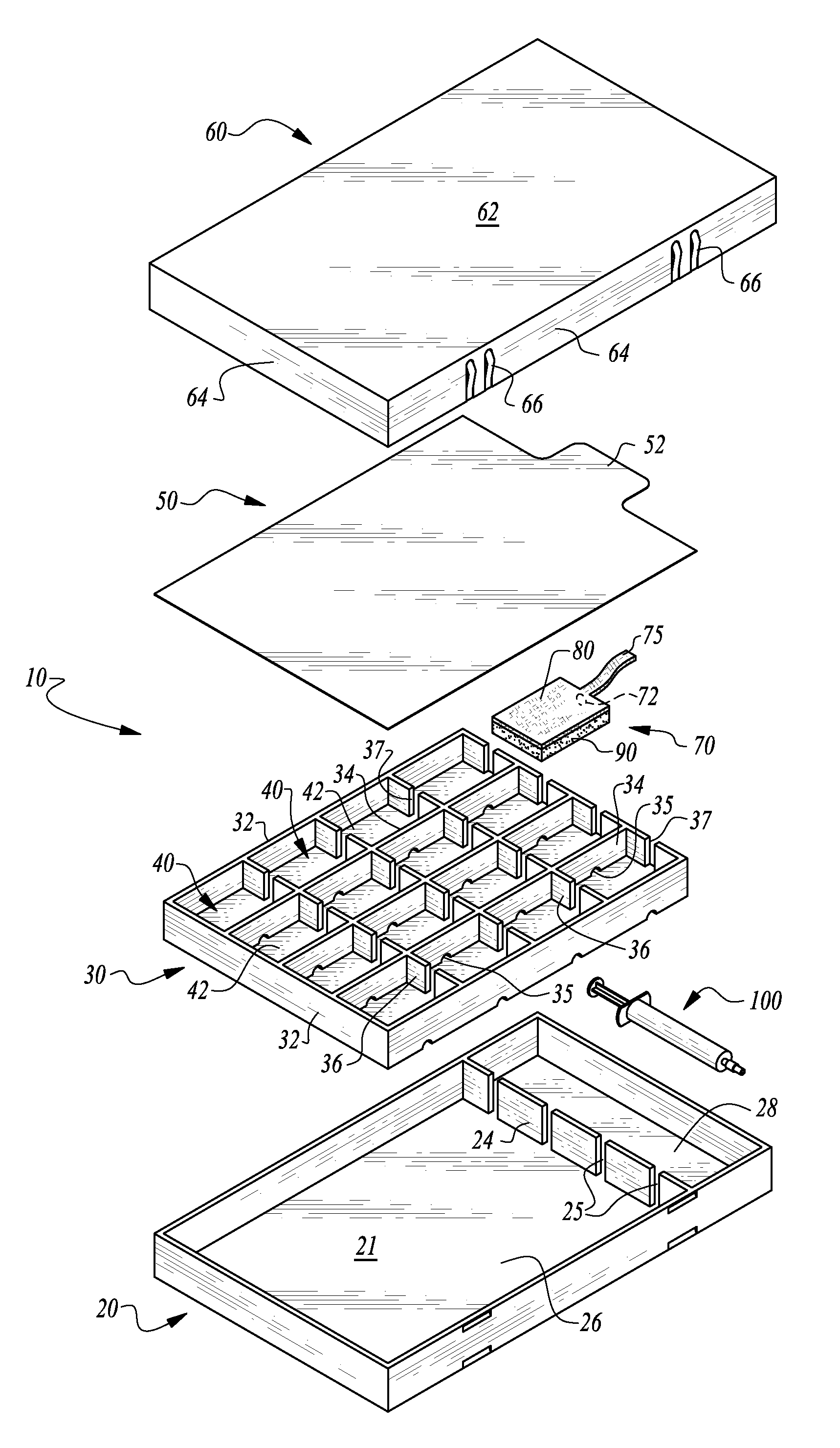
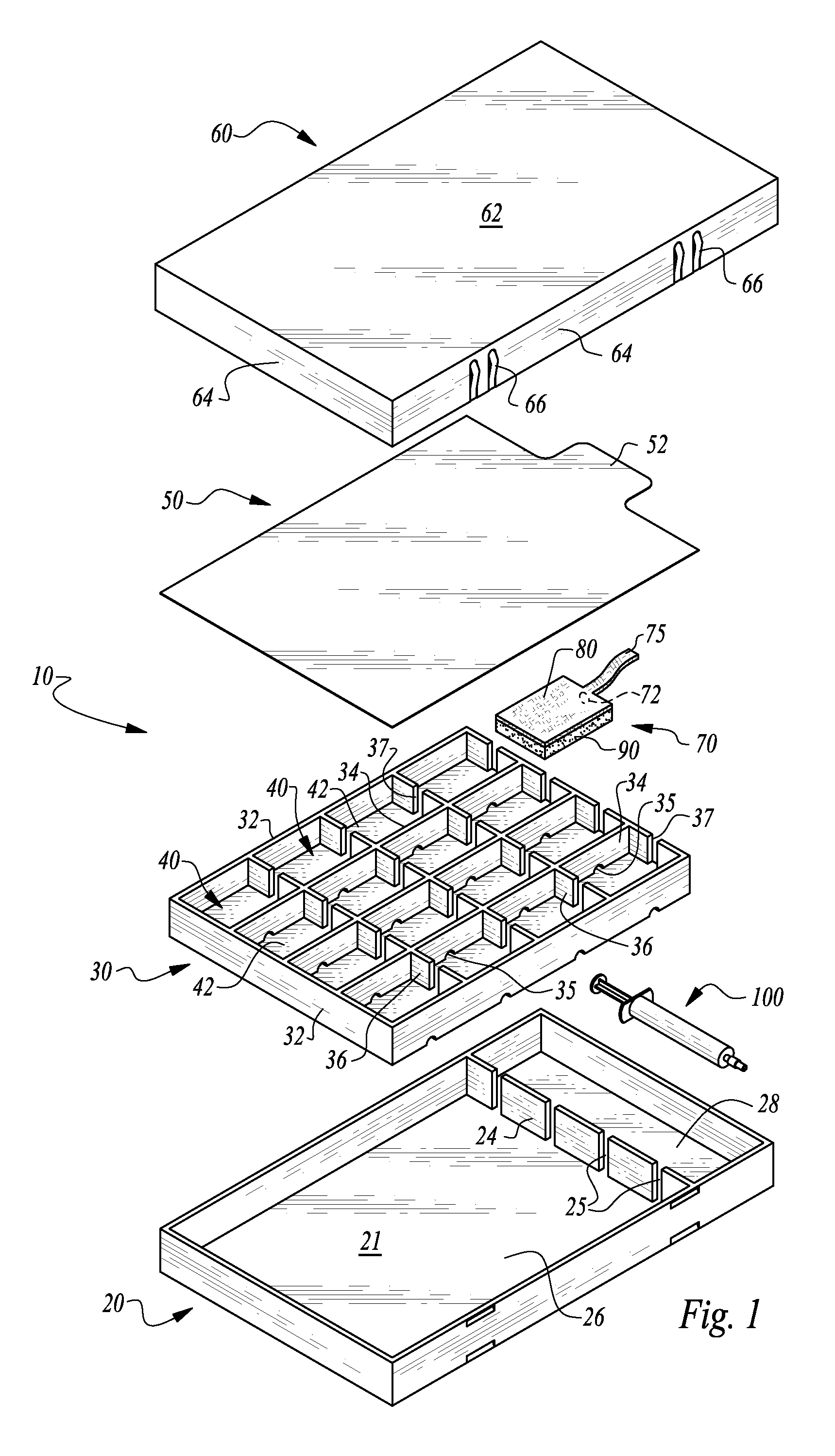
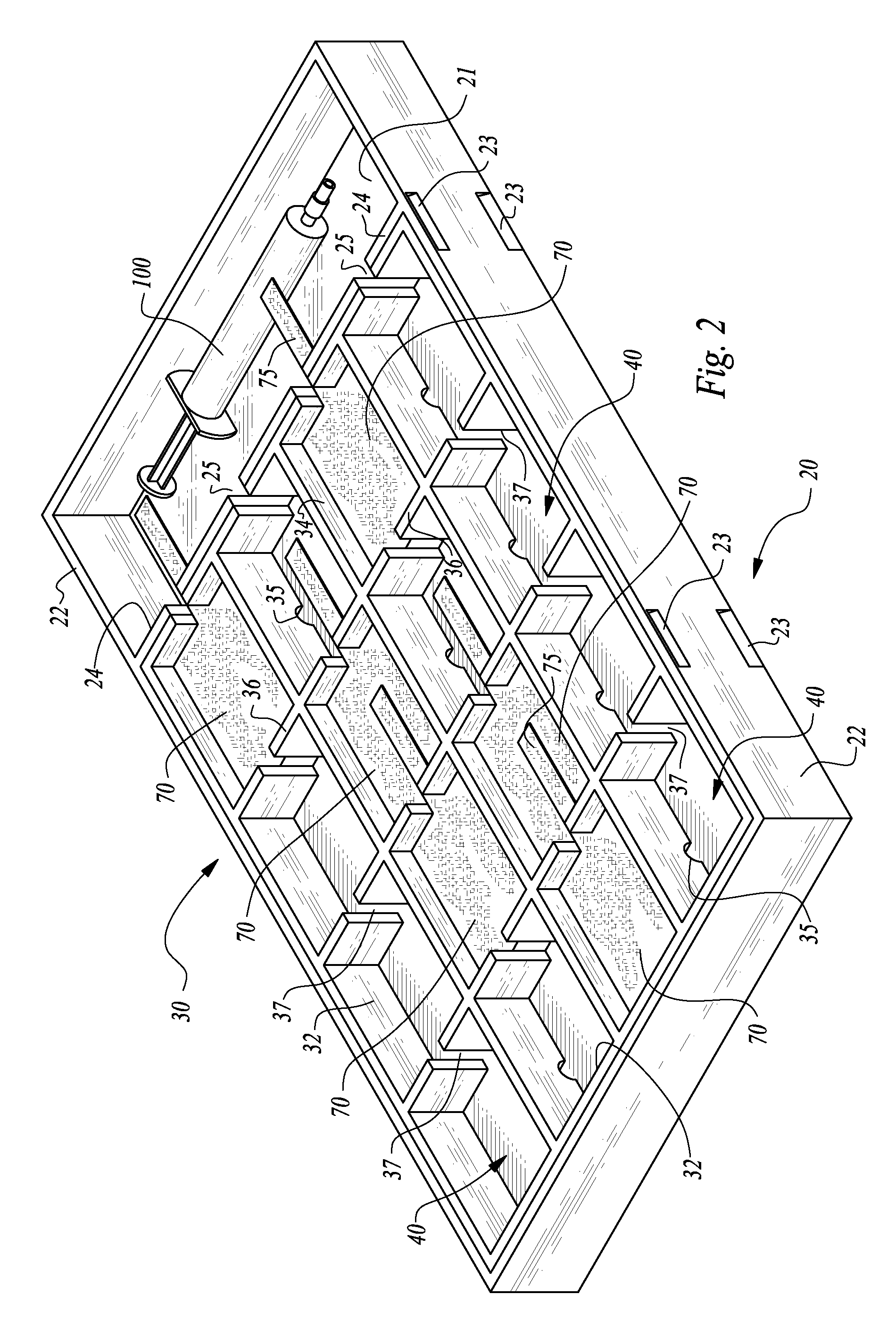
[0021]Referring to the drawings, wherein like reference numerals represent like parts throughout the various drawing figures, reference numeral 10 is directed to a kit in the form of a tray with included pads 70 and a syringe 100 provided together for use during surgical procedures to assist in bleeding control. The kit 10 is opened, such as by removing a cover 60 from a base 20 and removing a seal sheet 50. A syringe 100 can be preloaded or manually loaded separately with a bleeding control agent A (FIG. 5), such as a liquid thrombin or thrombin and saline solution. This bleeding control agent A is then expressed from the syringe 100 into the tray in a manner causing compartments 40 within an insert 30 resting upon a base 20 of the tray to each be flooded, and so that pads 70 within each compartment 40 are caused to be wetted with the bleeding control agent A. The pads 70 are then ready for use during the surgical procedure when bleeding control is desired. After use of the pads 70...


PUM


Abstract

A kit is provided including a base with an insert which has a plurality of compartments therein. The compartments are in fluid communication with each other. Liquid bleeding control agent is expressed into the base and allowed to flow to each of the compartments, such as through ports and inside slots between adjacent compartments. Pads reside within each of the compartments, which each include a gauze portion and a gel foam portion. The gel foam portion is wetted by the liquid bleeding control agent, which can be expressed from a syringe provided as a portion of the kit and which flows into the compartments for uniform wetting of gel foam portions of each of the pads. Pads are used during a surgical procedure and then returned to vacant compartments, so that a quick check for remaining vacant compartments indicates whether or not any pads have remained within the surgical site.

Description

CROSS-REFERENCE TO RELATED APPLICATIONS[0001]This application claims benefit under Title 35, United States Code §119(e) of U.S. Provisional Application No. 61 / 575,638 filed on Aug. 25, 2011.FIELD OF THE INVENTION[0002]The following invention relates to containers for holding surgical bleeding control pads and for assisting in wetting the pads with a bleeding control agent and accounting for the pads which have been used during a surgical procedure.BACKGROUND OF THE INVENTION[0003]When conducting surgery, one ongoing activity is the controlling of excessive bleeding. In many instances, a surgeon spends as much time controlling bleeding as in performing activities for which the surgery is required. It is desirable to perform the bleeding minimization steps associated with the surgery as simply and efficiently as possible to decrease the length of the surgery and best utilize the time and skills of the surgeon.[0004]In the prior art, bleeding control can be facilitated by small patches...

Claims


Application Information

Patent Timeline
Patent Type & Authority Patents(United States)
IPC IPC(8): A61F13/00A61B19/02
CPCA61B19/029A61F13/00029A61F13/00051A61B50/37
Inventor LIGHT, KENNETHSHEVICK, BARRY L.
Owner LIGHT KENNETH DR
Why Eureka
Try Eureka