Set comprising an intervertebral implant for immobilising a vertebra with respect to another and an instrument for installing this implant

a technology for immobilising a vertebra and a set is applied in the field of set comprising an intervertebral implant and an instrument for installing the implant, which can solve the problems of revealing certain anatomical structures, relative risk of implementation, and inability of orthopaedic surgeons or neurosurgeons to mobilise, so as to achieve precise and controlled side pivoting and facilitate separation from the implant

Inactive Publication Date: 2015-08-11
MEDICREA INT SA
View PDF4 Cites 64 Cited by
  • Summary
  • Abstract
  • Description
  • Claims
  • Application Information

AI Technical Summary

Benefits of technology

[0012]The main purpose thereof is therefore to provide a set that allows easy release of the implant, without substantial change of the position of the implant during withdrawal of the instrument.
[0038]An easy actuation of the instrument is thus obtained along with a simple structure and easy to sterilise.

Problems solved by technology

This technique has the drawbacks of being relatively risky to implement, involving achieving a bone resection of the vertebra near the spinal cord, and forcing the use of reduced width implants, allowing only a small area of contact of the grafts with the vertebrae.
An initiation through an anterior approach, however, has the disadvantage of revealing certain anatomical structures (in particular veins and arteries) that the orthopaedic surgeon or neurosurgeon is not accustomed to mobilise.
This approach will therefore not be possible for a spine surgeon unless he is assisted by a colleague whose specialty is, for example, vascular surgery.
The known instruments do not satisfy fully.
In fact, the release of the implant can be difficult and achieve and lead to a change of the position of the implant during withdrawal of the instrument.
The side pivoting of the implant with respect to the rod can be difficult to achieve or to control accurately, which can lead to a non optimal positioning of the implant in the intervertebral space.
There is also a risk of longitudinal pivoting of the implant about itself during the operation of introducing this implant, leading to a faulty positioning of the implant; this faulty positioning is difficult to overcome once the implant is pivoted laterally or released.

Method used


Image

  • Set comprising an intervertebral implant for immobilising a vertebra with respect to another and an instrument for installing this implant
  • Set comprising an intervertebral implant for immobilising a vertebra with respect to another and an instrument for installing this implant
  • Set comprising an intervertebral implant for immobilising a vertebra with respect to another and an instrument for installing this implant

Examples


Embodiment Construction

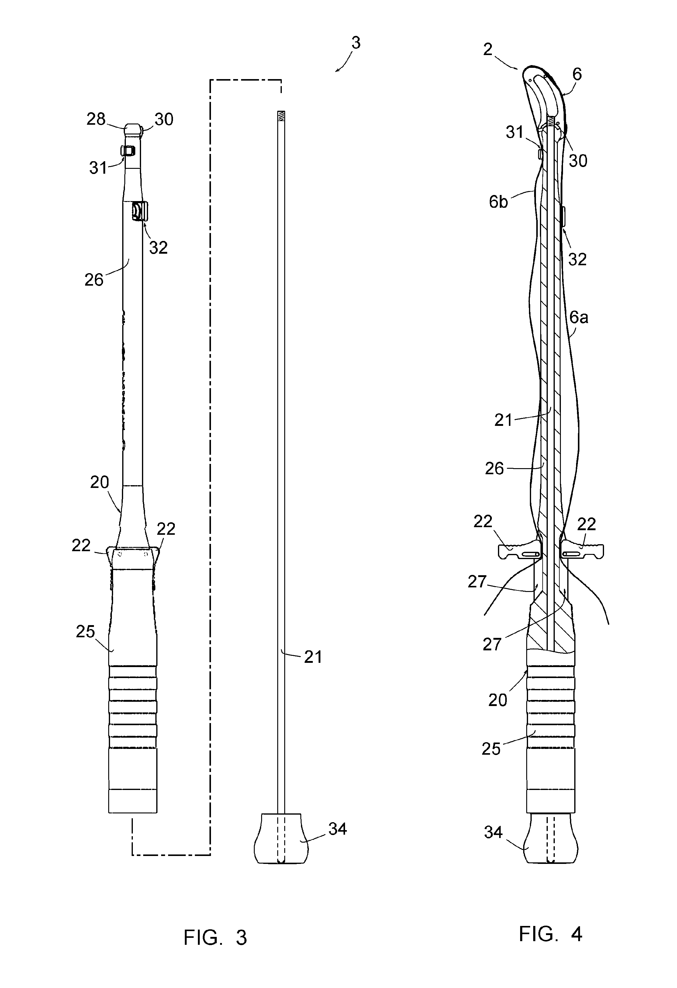
[0064]FIGS. 9 to 11 represent a set 1 comprising an intervertebral implant 2 allowing immobilising a vertebra 100 with respect to the overlying vertebra 100 and an instrument 3 of positioning this implant 2 between the plateaus 101 of the two vertebrae.

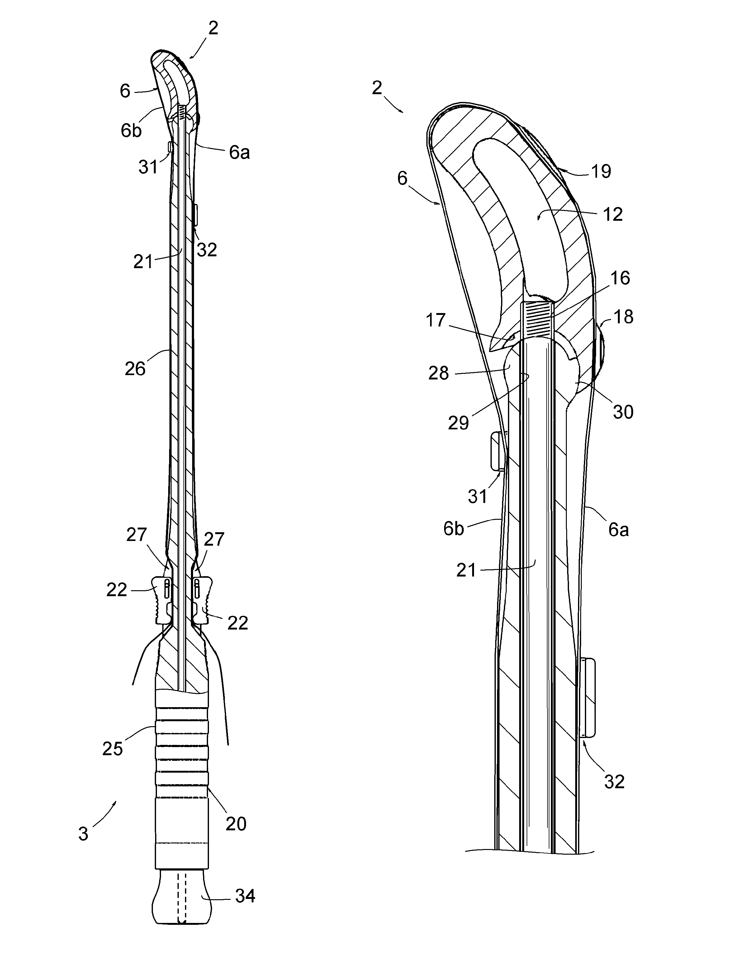
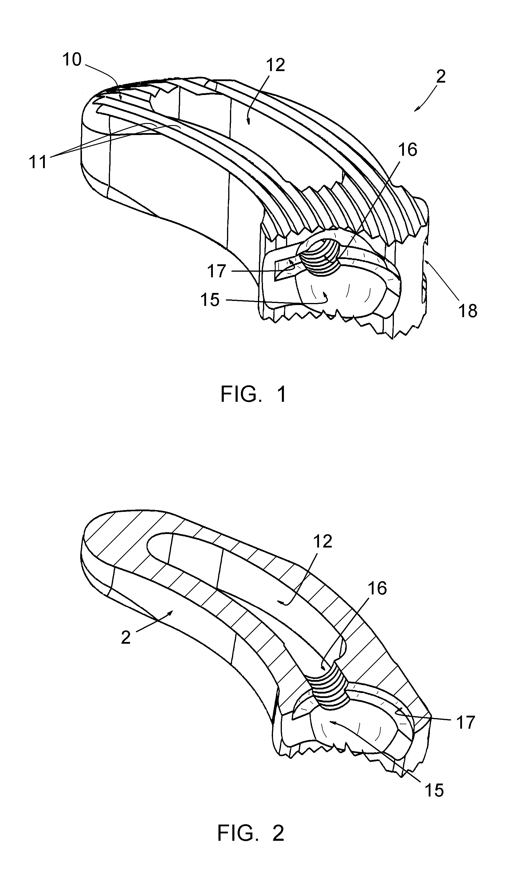
[0065]As shown more particularly in FIGS. 1 and 2, the implant 2 is designed to be inserted between the plateaus 101 of the two vertebrae 100 to be immobilised and is connected to a flexible link or ligament 6 forming two strands 6a, 6b exceeding from this implant.

[0066]The implant 2 has a curved shape substantially corresponding to the curvature shown by the anterior surface of the element of a vertebra 100 and such length that it occupies, once positioned in place, between the plateaus 101, a portion of the area of these plateaus along this anterior approach (see FIGS. 9 to 11). Moreover, it has such a width that it can be introduced into the intervertebral space to be treated by posterior approach, as shown, by side approach or int...


PUM


Abstract

This set comprises an intervertebral implant (2) for immobilising a vertebra (100) with respect to another and an instrument (3) for installing this implant; the implant (2) comprises a longitudinal end designed to be connected to the instrument (3), and the instrument (3) comprises a rod (26) having a free distal end (28), wherein the implant (2) is designed to be removably mounted. According to the invention: —said free distal end (28) of the instrument rod (26) is rounded; —the instrument (3) comprises releasable means (22) adapted, in a position, to retain the flexible strands (6a, 6b) in strain on each side of said rod (26), according to equivalent strains, and, in another position, to fully free these strands (6a, 6b); and—the means for mounting the implant (2) on said distal end (28) are constituted by the two flexible strands (6a, 6b) held in strain by said releasable means (22), this retaining in strain allowing to achieve mounting of the implant (2) on this distal end (28), while retaining this distal end (28) engaged in a cavity (15) of the implant (2).

Description

CROSS REFERENCE TO RELATED APPLICATION[0001]This application is a national stage entry of PCT / IB2010 / 053363 filed Jul. 23, 2010, under the International Convention, claiming priority over FR 0955238 filed Jul. 27, 2009.BACKGROUND OF THE INVENTION[0002]This invention relates to a set comprising an intervertebral implant for immobilising a vertebra with respect to another and an instrument for installing this implant.[0003]The invention also relates to a surgical method for immobilising a vertebra with respect to another.[0004]It is well known to immobilise two vertebrae one with respect to another by means of an intervertebral implant in a rigid material, forming a cage defining a housing, this housing being designed to receive one or more bone grafts and / or cancellous bone chips. In some cases, the bone grafts and / or the cancellous bone chips can also be placed about the implant. The implant can restore a proper separation of the vertebrae and prevent a crash of a chip or more than ...

Claims


Application Information

Patent Timeline
Patent Type & Authority Patents(United States)
IPC IPC(8): A61F2/46A61F2/44A61F2/30
CPCA61F2/4465A61F2/4611A61F2002/30378A61F2002/30462A61F2002/30476A61F2002/30495A61F2002/30538A61F2002/30772A61F2002/30904A61F2002/4627A61F2002/4629A61F2220/0025A61F2220/0033A61F2220/0075A61F2250/0006
Inventor MANGIONE, PAOLOCHATAIGNER, HERVE
Owner MEDICREA INT SA
Why Eureka
Try Eureka