
Electrically pedal-assisted bicycle

a pedal-assist bicycle and electric technology, applied in the direction of bicycles, battery/cell propulsion, transportation and packaging, etc., can solve the problem of limited range and achieve the effect of increasing the range of bicycles and less effor

Active Publication Date: 2015-08-11
POLITECNICO DI MILANO +2
View PDF14 Cites 2 Cited by
  • Summary
  • Abstract
  • Description
  • Claims
  • Application Information

AI Technical Summary

Benefits of technology

The system provides a comfortable riding experience with reduced cyclist effort, automatically managing energy use to maintain a stable battery state, increasing the bicycle's range and eliminating the need for external recharging.

Problems solved by technology

Such bicycles have the disadvantage to have a limited range, because in case of an extended use of the bicycle the used battery discharges and thus it is necessary to recharge the battery by means of the electric network.

Method used


Image

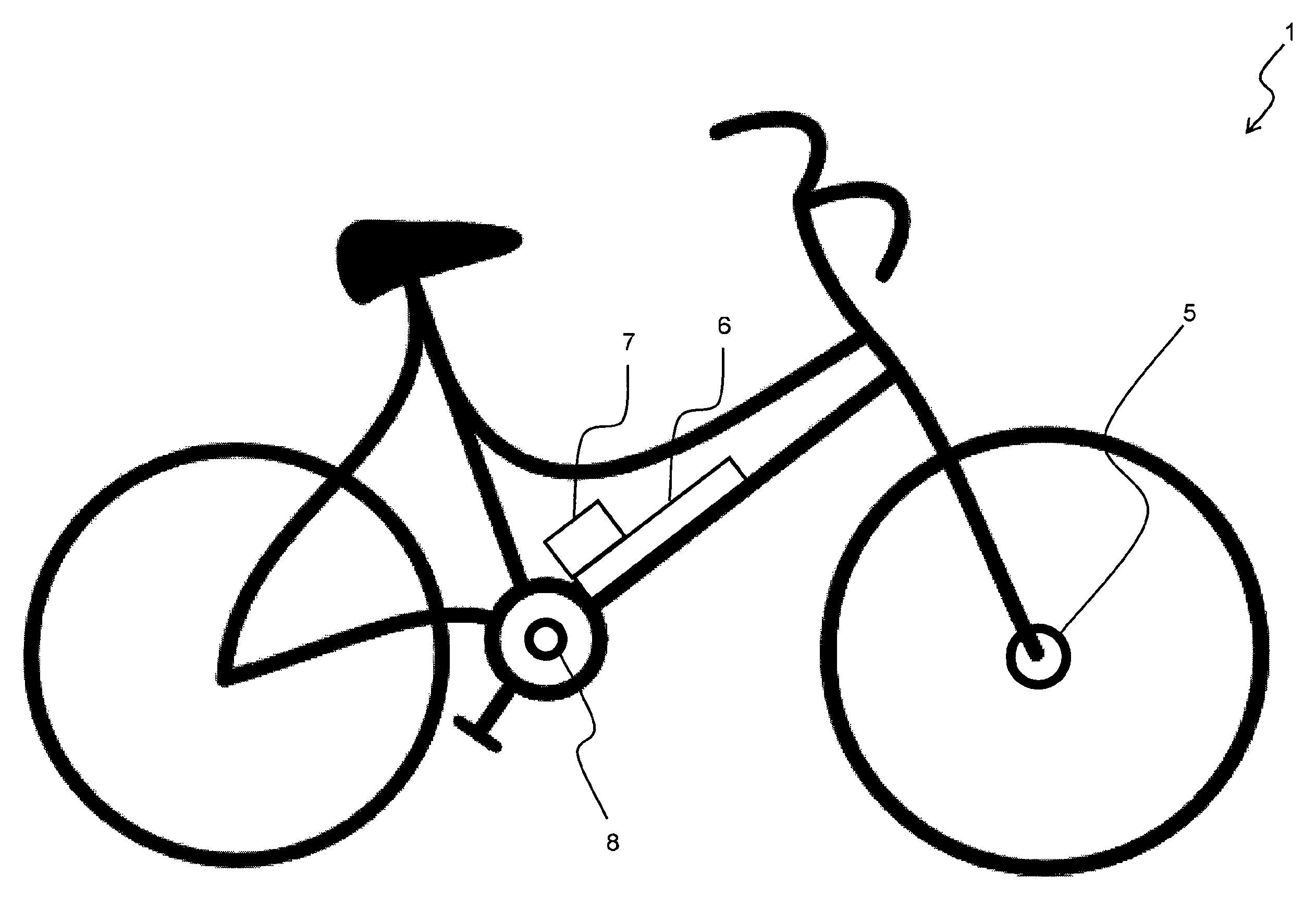
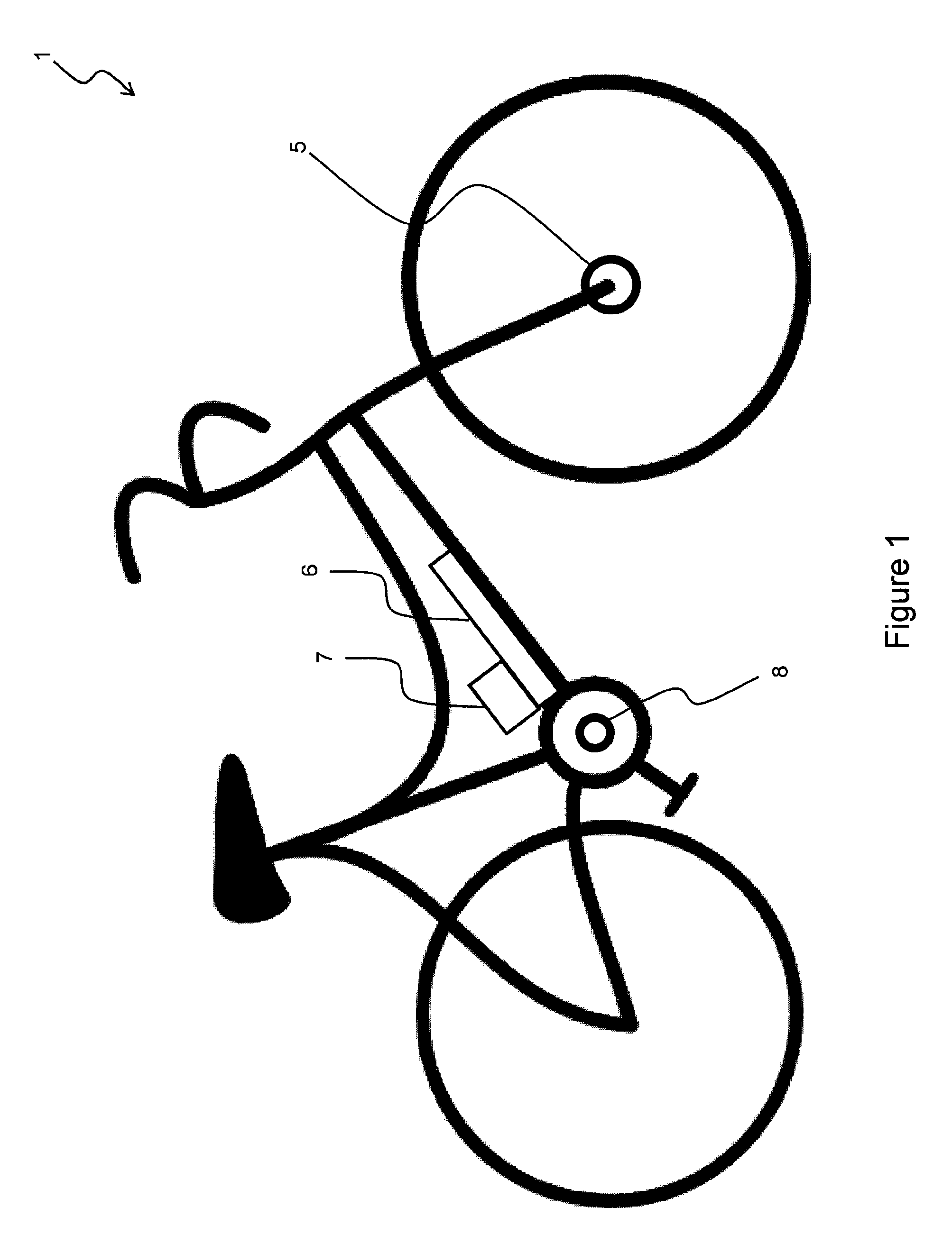
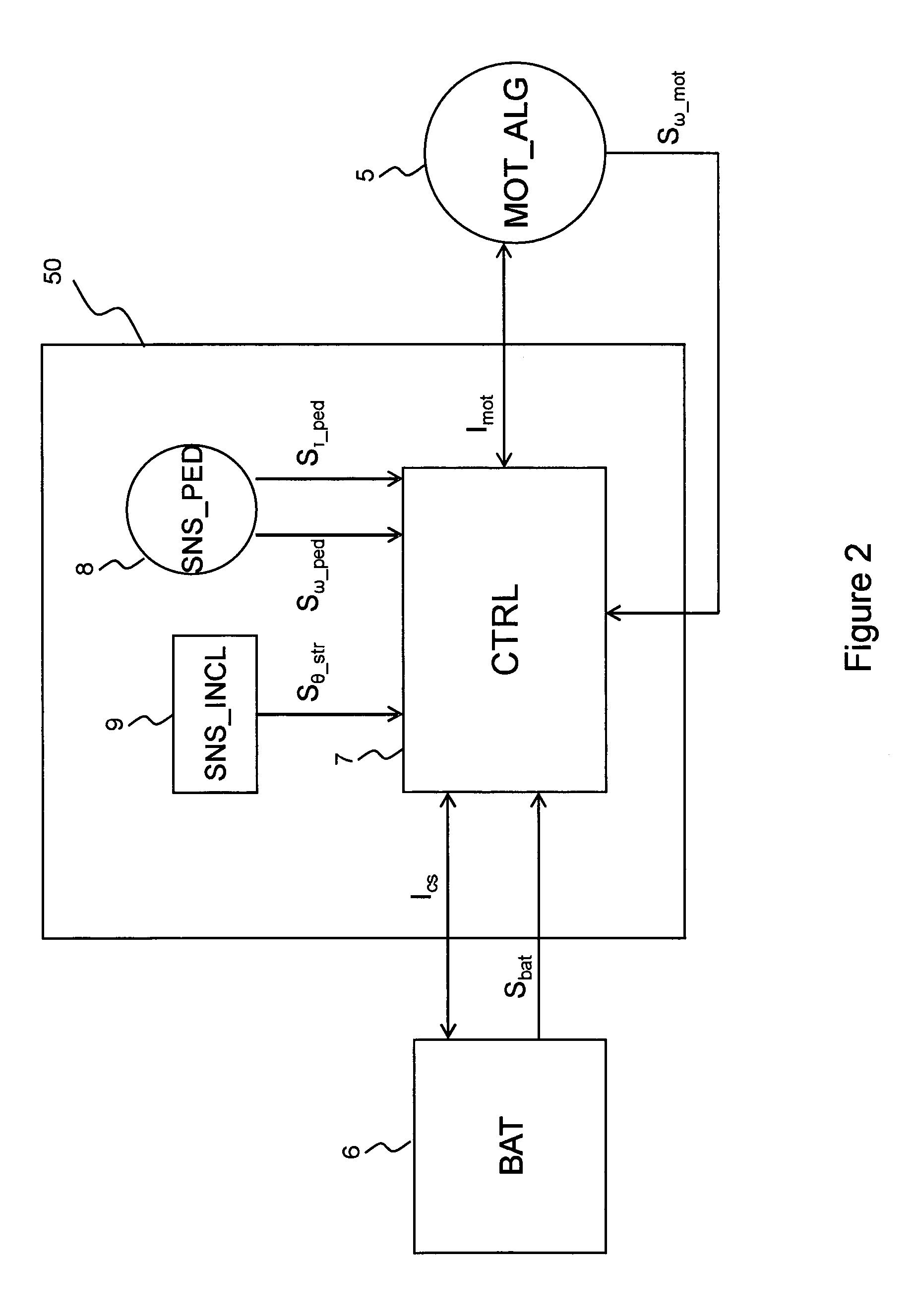
  • Electrically pedal-assisted bicycle
  • Electrically pedal-assisted bicycle
  • Electrically pedal-assisted bicycle

Examples


first embodiment

[0052]Referring to FIG. 4a, it is shown schematically a flow chart of the method 100 for driving the electric device of the electrically assisted bicycle 1 according to the invention.

[0053]The method 100 comprises the steps 101, 103, 105.

[0054]In step 101 it is performed the comparison between the human power Pum with respect to the friction power Pattr: in case the human power is greater than or equal to the friction power, it is performed the step 103, otherwise it is performed the step 105.

[0055]The term human power Pum means the power generated by the cyclist on the pedal arms of the bicycle 1 when the cyclist is pedaling; in other words, it is the effort performed by the cyclist when he is pressing on the pedal arms with his feet. For example, the human power Pum is calculated with the following formula (1):

Pum=Tped*ωped  (1)

[0056]Wherein Tped is the torque generated by the cyclist on the pedal arms of the bicycle 1 and ωped is the angular velocity of the pedal arms of the bicy...

second embodiment

[0073]Referring to FIG. 4b, it is schematically shown a flow chart of a method 150 for driving the electric device of the electrically assisted bicycle 1 according to the invention. It has to be observed that in FIG. 4b steps and symbols equal to the ones of FIG. 4a are indicated with the same reference numbers.

[0074]The method 150 comprises the steps 101, 102, 153, 154, 105.

[0075]In the step 101 it is performed the comparison between the human power Pum and the friction power Pattr: in case wherein the human power is greater than or equal to the friction power, it is performed the step 102, otherwise it is performed the step 105.

[0076]In the step 102 it is evaluated the slope θstr of the road (in other words the slope of the ground) wherein the bicycle 1 is running. When the slope of the road θstr is greater than zero (that is the cyclist is running along an uphill road) or equal to zero (that is the cyclist is running along an flat road), it is performed step 153. In the case wher...


PUM


Abstract

It is described an electronic system (50) to drive an electric device (5) of a bicycle assisted electrically (1) by means of a rechargeable battery (6). In case of detecting that the calculated human power is greater than or equal to the bicycle estimated friction power and in case of detecting that the state of charge of the battery (6) is greater than or equal to a first threshold, the processor is such to generate a driving current value for driving the electric device (5) operating as an electric motor (5) supplied from the battery (6). In case of detecting that the calculated human power is smaller than the estimated bicycle friction power, the processor is such to convert at least part of the human power into electric power by means of the electric device (5) operating as an electric generator (5), and generate therefrom another driving current value for charging the battery (6) from the electric device operating as electric generator.

Description

TECHNICAL FIELD OF THE INVENTION[0001]The present invention generally refers to the field of the electrical bicycles. More in particular, the present invention concerns an electrically pedal-assisted bicycle by means of rechargeable batteries.PRIOR ART[0002]Electrically pedal-assisted bicycles by means of batteries are known: see, for example, the European patents EP 1612084, EP 1886913. Such bicycles have the disadvantage to have a limited range, because in case of an extended use of the bicycle the used battery discharges and thus it is necessary to recharge the battery by means of the electric network.[0003]European patent nb. 1236640-B1 claims the priority of Japanese patent application having publication nb. 2002 / 255080, publication date of Sep. 11, 2002, filing nb. 2001 / 055400 and filing date of Feb. 28, 2001 and claims the priority of Japanese patent application having publication nb. 2002 / 2550801, publication date of Sep. 11, 2002, filing nb. 2001 / 055401 and filing date of F...

Claims


Application Information

Patent Timeline
Patent Type & Authority Patents(United States)
IPC IPC(8): H02K7/00B60L11/00B62M6/50B60L15/20B60L11/18B60W10/26B62M6/45
CPCB60L11/1801B60L11/1877B60L15/2009B60L15/2045B60L15/2054B62M6/50B60L11/007B60W10/26B60L2200/12Y02T10/7005Y02T10/705Y02T10/7283B60L50/53B60L50/20B60L50/66Y02T10/64Y02T10/70Y02T10/72
Inventor SPELTA, CRISTIANOALLI, GIOVANNISPAGNOL, PIERFRANCESCOSAVARESI, SERGIO MATTEOVANZULLI, MASSIMOBIESUZ, GIUSEPPE
Owner POLITECNICO DI MILANO
Learn More