Magnified solar energy generator

a solar energy generator and solar energy technology, applied in the direction of machines/engines, heat collector mounting/support, light and heating equipment, etc., can solve the problem that no one can teach a system as unique as the on

Inactive Publication Date: 2015-08-11
KILGORE RICHARD D
View PDF18 Cites 6 Cited by
  • Summary
  • Abstract
  • Description
  • Claims
  • Application Information

AI Technical Summary

Problems solved by technology

While the known commercial and published patents reveal a number of systems for producing solar energy, none teach a system as unique as the one herein described.

Method used


Image

  • Magnified solar energy generator
  • Magnified solar energy generator
  • Magnified solar energy generator

Examples


Embodiment Construction

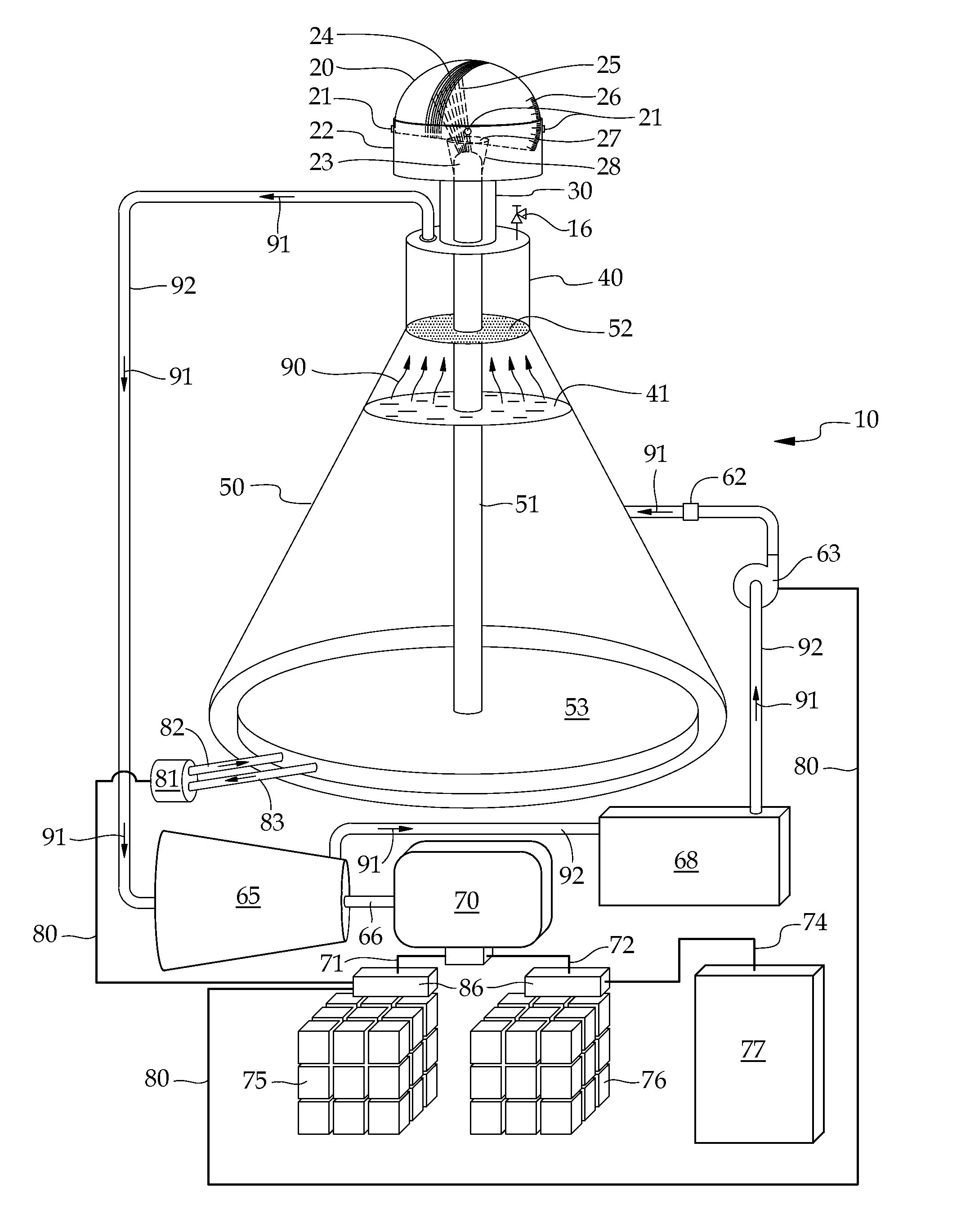
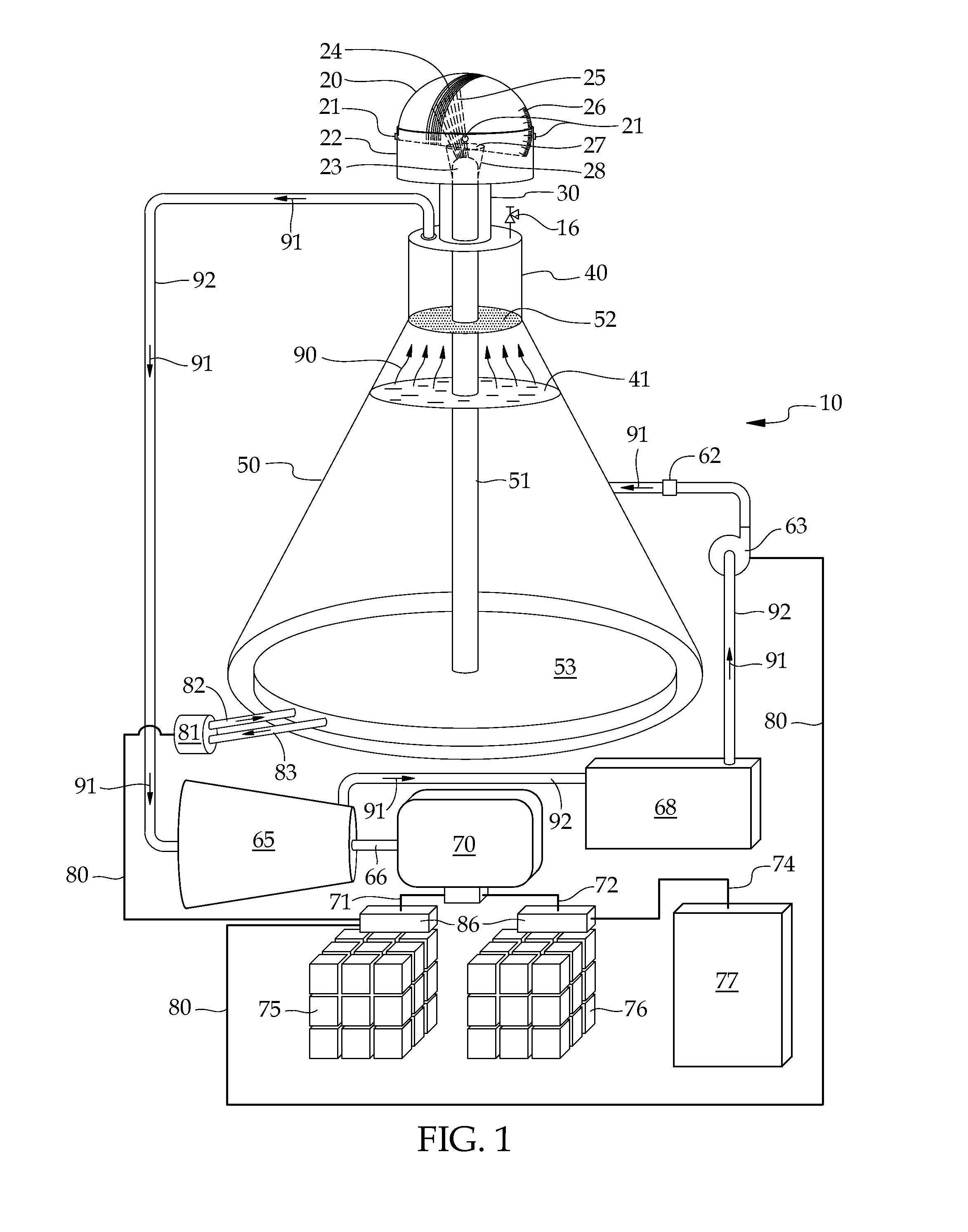
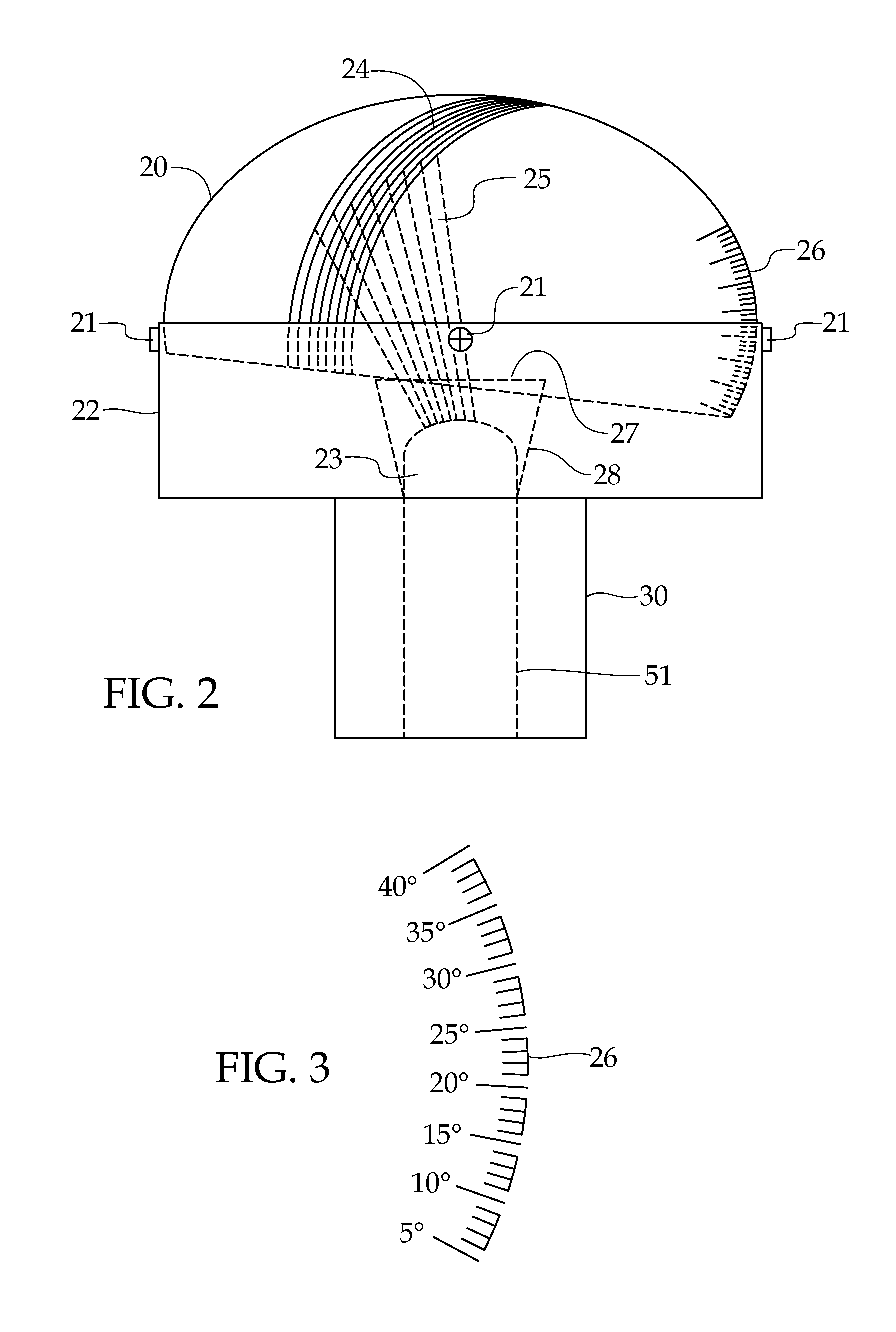
[0028]The following discussion describes in detail at least one embodiment of the present invention. This discussion should not be construed, however, as limiting the present invention to the particular embodiments described herein since practitioners skilled in the art will recognize numerous other embodiments as well. For a definition of the complete scope of the invention the reader is directed to the appended claims. FIGS. 1 through 7 illustrate the present invention wherein a solar energy generating system is disclosed and which is generally indicated by reference number 10.

[0029]The present invention 10 is directed to a solar energy generating system that uniquely combines plural components that are not known with conventional commercial systems, along with several conventional components that are known and used in such commercial systems.

[0030]The following written description makes reference generally to all the FIGS. 1-7 and may reference specific Figures which will be indi...


PUM


Abstract

Method and apparatus for a solar energy generating system to provide electricity to a structure ranging from a single family dwelling to multi-unit dwellings to commercial buildings, or a power plant or power grid. The system includes a solar collector having a magnifying lens to direct and focus sun rays to a solar energy collector, a heat transfer unit, boiler, a water heater backup system, a condenser unit and steam engine, and plural electrical energy storage units to store and dispense electricity to the selected type of electricity user.

Description

RELATED APPLICATIONS[0001]This application is a continuation-in-part of U.S. patent application Ser. No. 13 / 136,879 dated Aug. 15, 2011.BACKGROUND OF THE INVENTION[0002]1. Field of the Invention[0003]The present invention relates generally to solar energy generating systems and, more particularly, is concerned with a solar energy generator that incorporates a plurality of unique components to more efficiently produce cost effective electricity.[0004]2. Description of the Related Art[0005]The present invention relates to a magnified solar generator system offering improved efficiency by the use of a combination of components unique to the solar production of electricity. The system of this invention has particular utility to residential building structures where the preferred system is suited best for single family homes. Notwithstanding the preferred application, it will be understood that the system hereof is also suitable to multi-unit structures, commercial buildings and new or e...

Claims


Application Information

Patent Timeline
Patent Type & Authority Patents(United States)
IPC IPC(8): F03G6/00F03G7/00F03G6/06F24J2/04F24J2/06F24J2/24F24S10/70F24S23/00
CPCF03G6/065F24J2/04F24J2/06F24J2/24F03G6/003Y02E10/46Y02E10/44Y02B10/20Y02E10/47F24S2080/503F24S20/20F24S25/70F24S23/30F24S10/00F24S10/70Y02E10/40
Inventor KILGORE, RICHARD D
Owner KILGORE RICHARD D
Why Eureka
Try Eureka