Solar Heat Collector, Sunlight Collecting Reflector, Sunlight Collecting System and Solar Energy Utilization System

a solar energy utilization system and solar heat collector technology, applied in the direction of machines/engines, transportation and packaging, light and heating equipment, etc., can solve the problems of difficult to finely control the temperature by flow control, limited sunlight utilization efficiency, and inability to optimize the shape of the heat collector, so as to achieve efficient use of stored thermal energy and efficiently collect sunlight reflected

Active Publication Date: 2009-07-09
TOKYO INST OF TECH
View PDF13 Cites 87 Cited by
  • Summary
  • Abstract
  • Description
  • Claims
  • Application Information

AI Technical Summary

Benefits of technology

[0088]In the solar energy utilization system, the sunlight collecting reflector can efficiently collect the sunlight reflected to the light collecting point by the plurality of the first reflectors. In addition, the collected sunlight can be made converge on the solar heat collector according to the first aspect B of the present invention. Then, energy of the converging sunlight can be stored in the heat exchange medium which gravitationally flows down as a liquid film so that the stored thermal energy can be efficiently used.

Problems solved by technology

Therefore, an efficiency of sunlight utilization is limited.
However, in Non-Patent Documentation 2, there is no discussion about optimizing the shape of the heat collector.
Therefore, it is difficult to finely control the temperature by flow control.
In addition, it is difficult to produce a large-scale apparatus in such a complicated shape as double truncated cones so that it is difficult to achieve practical and commercial utilization.
However, in a light collecting system in which heliostats are installed within an area of 100 m in radius, a radius of the light collecting reflector 62 is several tens meters or more, and installation height is approximately 100 m. In this case, the reflector is subject to a high wind pressure.
Moreover, a structure to support the reflector needs to be firmly constructed to stand against the strong wind during stormy weather, so as to cause a construction cost to increase.
However, in these methods, it is impossible to use the sunlight which is collected by the heliostats and reaches in portions of the spaces between the reflectors.
Moreover, 2) due to shortage of light collection caused by above-mentioned 1), when the molten salt collects heat in the heat collector 63, a temperature of the molten salt rises insufficiently.
To equalize density of the heat fluxes is also a problem to be solved by the beam-down light collection method.
However, these sunlight collecting systems are systems still in experimental phases, in which a quantity of collected light is comparatively small.
Therefore, to construct a large-scale light collecting system which can collect a sufficient quantity of light to be used in a commercial scale, the systems cannot cope with the problems which occur as the systems are enlarged.
For instance, height where the heat collector or the reflector is installed is actually limited caused by influence of the wind pressure to which the heat collector or the reflector is subject.
Therefore, when the light collecting system is installed in the northern hemisphere for instance, the number density of the heliostats is large on a south side of the tower causes the light collecting system to be inefficient (, that is, the number of heliostats required to obtain the same quantity of light increases).
As a result, the following problems also occur.
Such a problem that the efficiencies of the sunlight collection and utilization decrease as the light collecting system enlarges is more prominent in an enlarged light collecting system where the heliostats are distributed in a wider area, and a bottleneck to construct a large-scale light collecting system.

Method used


Image

  • Solar Heat Collector, Sunlight Collecting Reflector, Sunlight Collecting System and Solar Energy Utilization System
  • Solar Heat Collector, Sunlight Collecting Reflector, Sunlight Collecting System and Solar Energy Utilization System
  • Solar Heat Collector, Sunlight Collecting Reflector, Sunlight Collecting System and Solar Energy Utilization System

Examples


first embodiment

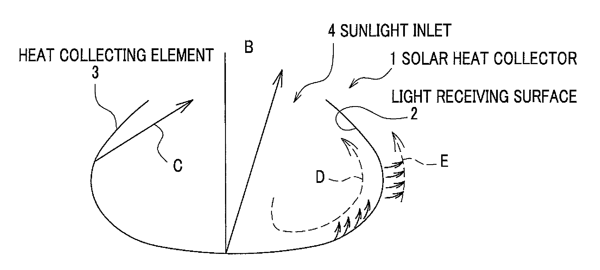
[0130]FIG. 1 is a schematic diagram showing an example of a solar heat collector according to a first embodiment of the invention.

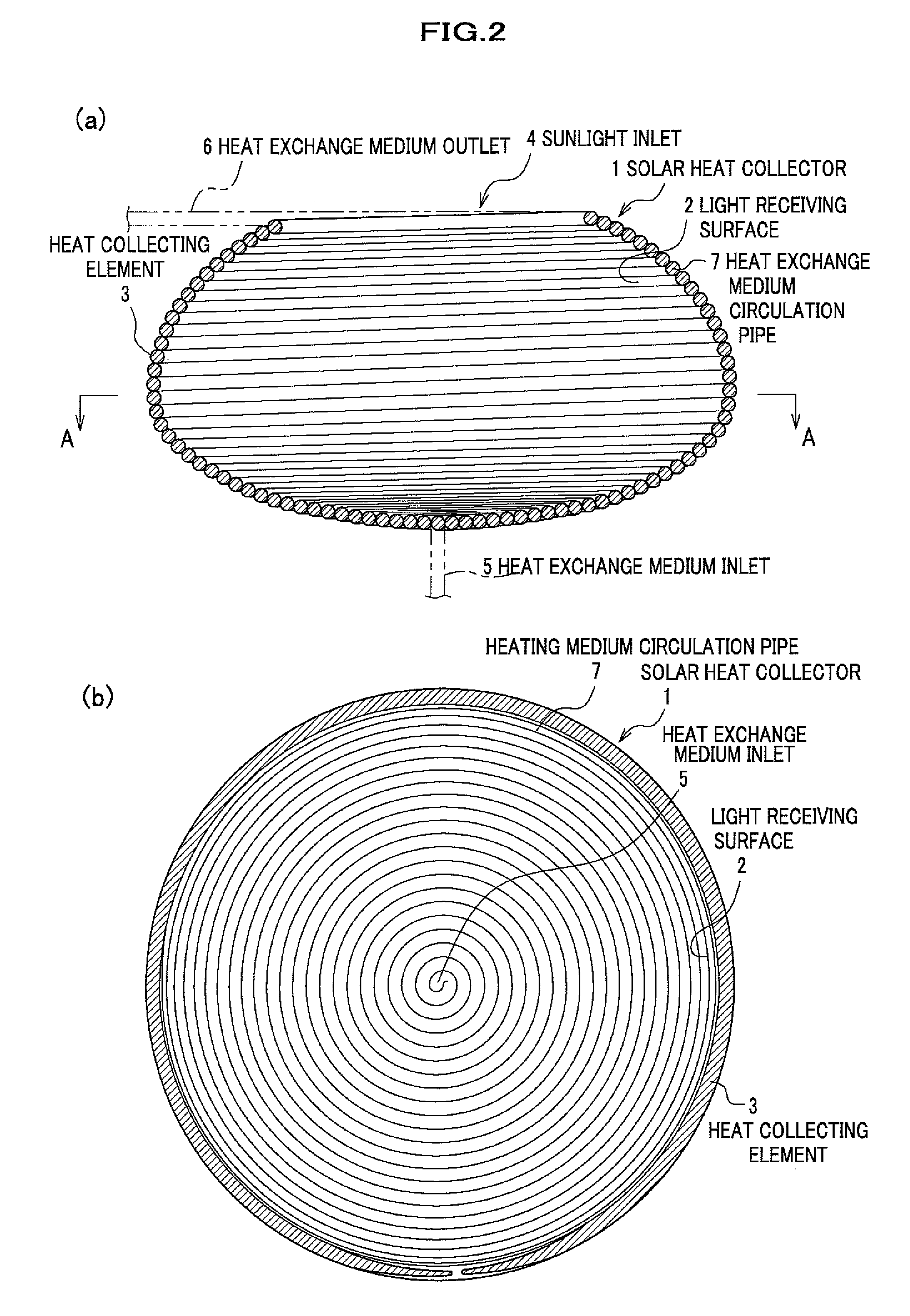
[0131]The solar heat collector 1 whose outline is shown in FIG. 1 includes a heat collecting element 3, a sunlight inlet 4 which is opened at an end of the heat collecting element 3, a heat exchange medium inlet 5 through which heat exchange medium is introduced into the heat collecting element 3, and a heat exchange medium outlet 6 as shown in FIG. 2(a).

[0132]The heat collecting element 3 is formed by a helically wound circulating heat exchange medium circulation pipe 7 inside which the heat exchange medium flows. Thus, a light receiving surface 2 is constituted of an outer peripheral side of the heat exchange medium circulation pipe 7 which is exposed inside the heat collecting element 3. Then, the light receiving surface 2 is incurved to narrow towards the sunlight inlet 4 which is opened at the end of the heat collecting element 3. The incurved shape ...

second embodiment

[0149]Next, FIG. 8 is a schematic diagram showing an example of a solar energy utilization system according to a second embodiment, which uses the solar heat collector 1 according to the first embodiment of the invention.

[0150]The solar energy utilization system shown in FIG. 8 includes a first light collecting system FC, a second light collecting system SC, a third light collecting system CPC, a solar heat collector 1, a high-temperature heat exchange medium tank 81, a heat exchanger 82, a low-temperature heat exchange medium tank 83, and a heat exchange medium purification system 84. Moreover, the solar heat collector 1, the high-temperature heat exchange medium tank 81, the heat exchanger 82, the low-temperature heat exchange medium tank 83, and the heat exchange medium purification system 84 are connected with each other by flow paths through which heat exchange medium circulates. In addition, valves, and so on are arranged in places.

[0151]A solar heat collector 1 similar to the...

third embodiment

[0157]Next, FIG. 9(a) is a schematic cross section showing a solar heat collector 91 according to a third embodiment of the invention.

[0158]The solar heat collector 91 shown in FIG. 9A includes a heat collecting element 93 whose inner surface constitutes a light receiving surface 92 where heat exchange medium gravitationally flows down as a liquid film, a sunlight inlet 94 which is opened on an upper end of the heat collecting element 93, a heat exchange medium inlet 95 through which the heat exchange medium is introduced into the heat collecting element 93, and a heat exchange medium outlet 96.

[0159]In the heat collecting element 93, thin plates are combined to form the light receiving surface 92 which receives sunlight SB on the inner surface and on which the heat exchange medium gravitationally flows down as a liquid film. Moreover, the light receiving surface 92 is incurved and narrows and converges towards the sunlight inlet 94 which is opened on the upper end of the heat colle...


PUM


Abstract

A sunlight collecting system and a solar energy utilization system which collects sunlight with the sunlight collecting system are provided, a sunlight collecting system including a solar heat collector which includes a heat collecting element which is formed by a helically wound heat exchange medium circulation pipe inside which the heat exchange medium flows, in such a way to have an incurved light receiving surface which narrows and converges towards the sunlight inlet and a sunlight collecting reflector which includes a reflector group which includes a plurality of reflector segments each of which includes a reflecting surface which makes sunlight converge on a heat collector, a sunlight collecting system in which a plurality of heliostats Bm are arranged in places which are irradiated by the sunlight between a plurality of heliostats An, in which each of the heliostats An and the heliostats Bm reflect light in a direction to a light collecting point of a heliostat group in which the heliostat is included.

Description

TECHNICAL FIELD[0001]The invention relates to a solar heat collector, a sunlight collecting reflector, a sunlight collecting system, and a solar energy utilization system, and more specifically, to a solar heat collector and a sunlight collecting reflector which efficiently use solar energy, a sunlight collecting system which efficiently collects sunlight, and a solar energy utilization system which efficiently uses thermal energy of collected sunlight.BACKGROUND ART[0002]In recent years, development and practical utilization are being promoted for a solar heat collector, a sunlight collecting system, and a solar energy utilization system which uses thermal energy of collected sunlight, as an apparatus or a system which uses thermal energy obtained from collected sunlight as a heat source for various kinds of systems and processes such as a power generation system and a chemical reaction process. For instance, there was a demonstration test of a light collecting system (in a tower m...

Claims


Application Information

Patent Timeline
Patent Type & Authority Applications(United States)
IPC IPC(8): F24J2/10F24S10/60F24S10/70F24S20/20F24S23/00F24S23/70F24S23/79
CPCF02C1/05F03G6/00F03G6/064F24J2/07F24J2/18F05D2250/25F24J2/24Y02E10/41Y02E10/44Y02E10/46F05D2240/40F24J2/23F24S10/60F24S10/70F24S20/20F24S23/79Y02E10/40
Inventor TAMAURA, YUTAKAYOSHIZAWA, YOSHIOUTAMURA, MOTOAKIHASUIKE, HIROSHIISHIHARA, HIDEYUKITAKAMATSU, TADAHIKO
Owner TOKYO INST OF TECH
Why Eureka
Try Eureka