Electrical generating system using solar energy and gas turbine

a technology of solar energy and gas turbines, applied in the direction of machines/engines, mechanical equipment, transportation and packaging, etc., can solve the problems of poor market acceptance, inability to compete with solar thermal generation facilities, and low solar fraction of total electric energy generated, etc., to achieve the effect of satisfying this need

Inactive Publication Date: 2006-08-10
SKOWRONSKI MARK
View PDF6 Cites 91 Cited by
  • Summary
  • Abstract
  • Description
  • Claims
  • Application Information

AI Technical Summary

Problems solved by technology

Although simple and reliable, such solar thermal generation facilities are inefficient and cannot compete, in most cases, with traditional fossil fuel generated electrical energy.
The ISCCS system, unfortunately, has been poorly received in the market because of several problems.
First of all, the solar fractional portion of the total electric energy generated is very low.
Thus, most ISCCS plants cannot qualify for various tax and other economic incentives provided by local governing bodies for renewable energy producing facilities.
Also, the heat recovery steam generator is inherently inefficient, since it must be carefully designed as a combined unit and cannot be efficiently operated when there is no solar heat addition.
Finally, the ISCCS is highly complex in design and operation, and is, for that reason, expensive to build, maintain and operate.

Method used


Image

  • Electrical generating system using solar energy and gas turbine
  • Electrical generating system using solar energy and gas turbine
  • Electrical generating system using solar energy and gas turbine

Examples


example

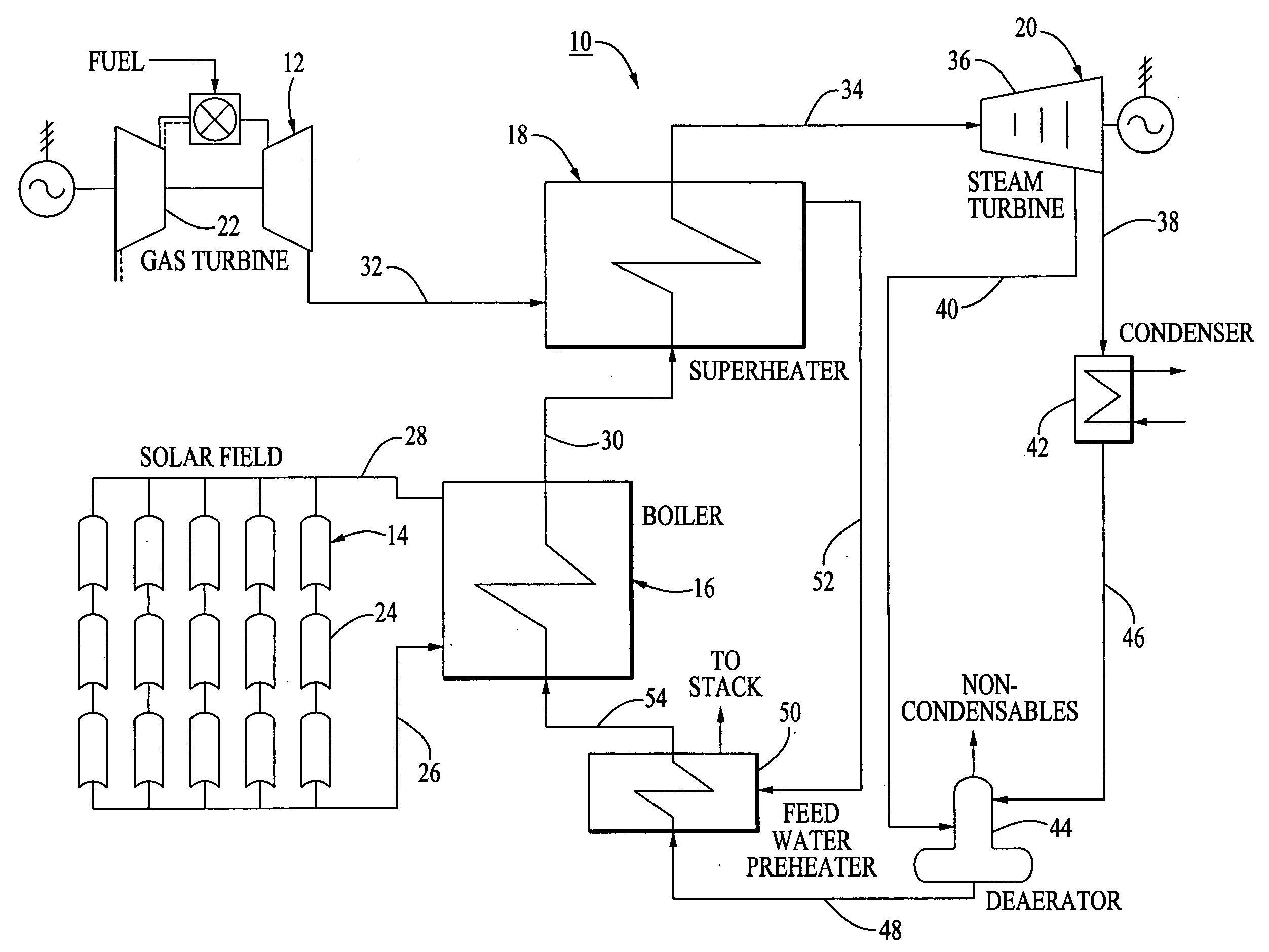
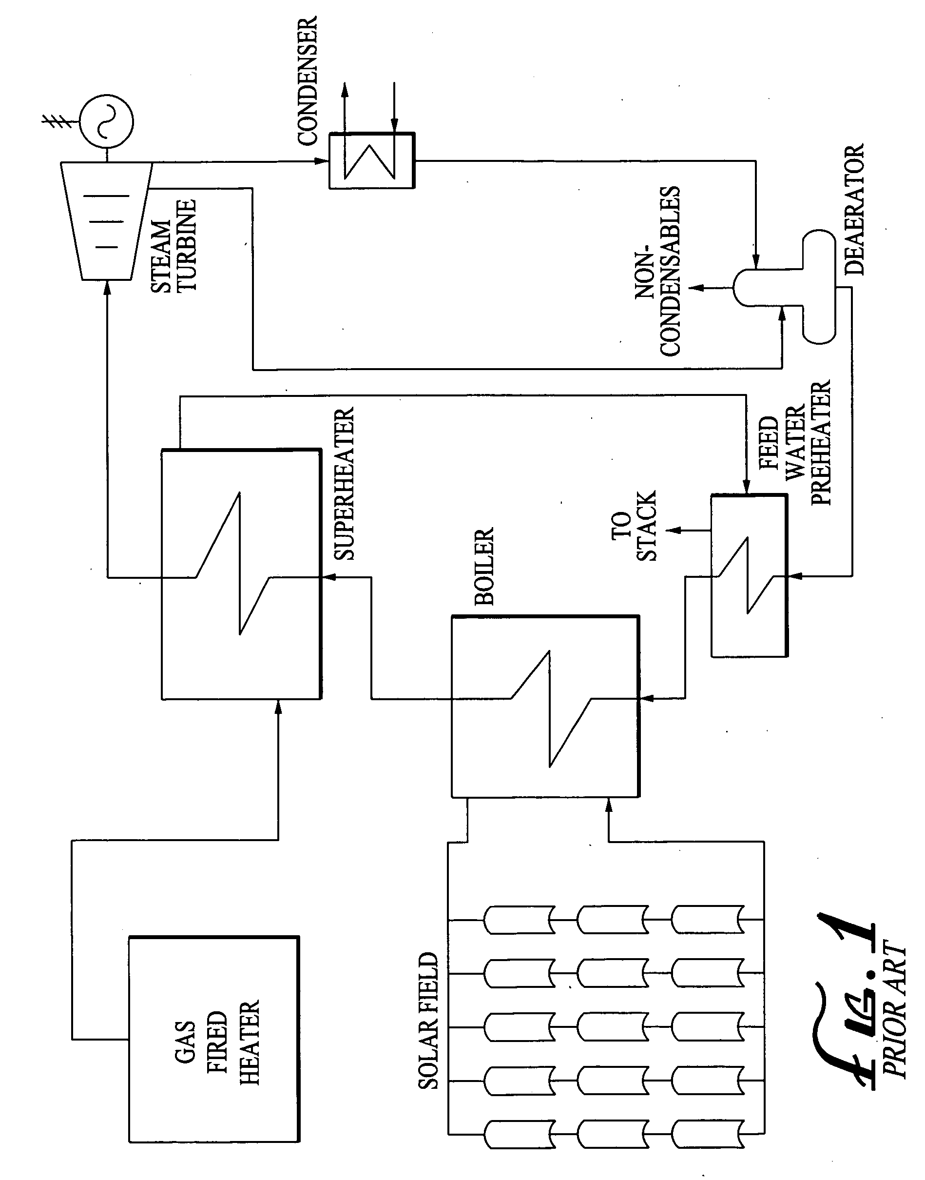
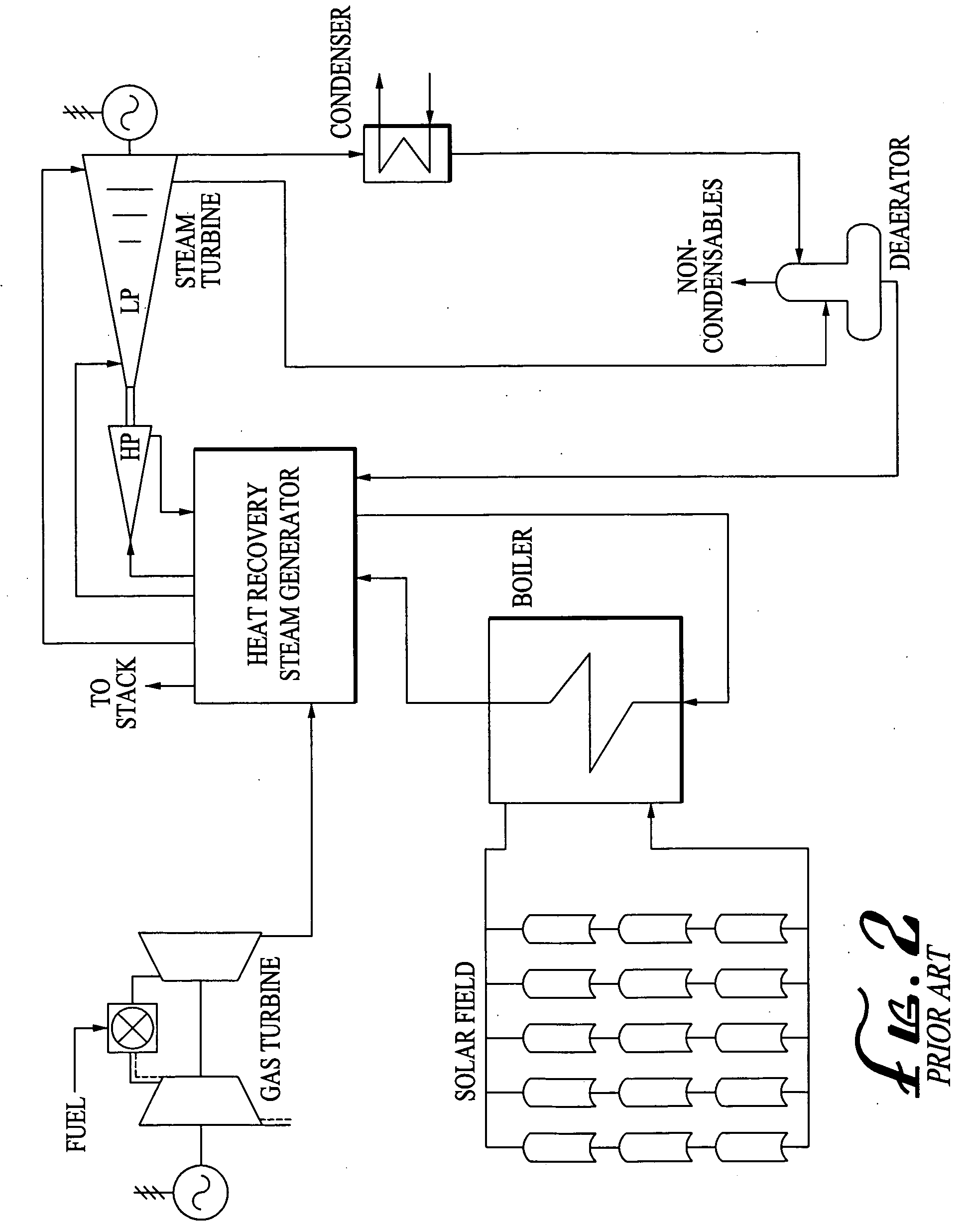
[0028] A hypothetical solar thermal regeneration system, such as illustrated in FIG. 1, was compared with a hypothetical ISCCS, such as illustrated in FIG. 2, and a hypothetical system of the invention, such as illustrated in FIG. 3.

[0029] In each hypothetical case, the solar field is estimated to be 540,000 square meters, capable of producing about 940 million BTU's per hour at peak on a summer day in a typical high solar insolation area.

[0030] The fossil fuel-fired heater in the solar thermal regeneration system illustrated in FIG. 1 is assumed to be 100 MW in size. The gas turbine electric generator in the ISCCS system is assumed to be 325 MW. The gas turbine electric generator in the apparatus of the invention as illustrated in FIG. 3 is assumed to be 247 MW.

[0031] The working gas vapor turbine electric generator used in the solar thermal regeneration system illustrated in FIG. 1 is assumed to be 100 MW in size. The working fluid vapor turbine electric generator in the ISCCS ...


PUM


Abstract

An apparatus for generating electricity using both solar energy and a gas turbine includes (a) a gas turbine electric generator; (b) a solar energy collector array; (c) a vaporizer for vaporizing a working fluid liquid, such as water, using thermal energy derived from the solar energy collector array; (d) one or more superheaters for superheating working fluid vapor produced in the vaporizer; and (e) a working fluid vapor turbine electric generator, such as a steam turbine electric generator, the working fluid vapor turbine electric generator being driven by the superheated working fluid vapor. The apparatus is configured such that all of the working fluid vapor exiting the one or more superheaters is that which is produced in the vaporizer.

Description

FIELD OF THE INVENTION [0001] This invention relates generally to electrical generating systems and, especially, to electric generated systems combining a solar energy field and a gas turbine electric generator. BACKGROUND OF THE INVENTION [0002] Solar thermal generation has the ability to generate clean, on-peak firm energy when used in conjunction with a fossil fuel for backup. Solar thermal generation is the only renewable source of energy which can be so easily hybridized and provide the premium energy desired by summer peaking utilities. Solar powered generation essentially follows the energy load of summer peaking utilities, thereby providing the on-peak energy when it is needed most. [0003] A typical solar thermal generation system is illustrated in FIG. 1 and consists of a traditional steam Rankine cycle with gas assist to provide energy during cloudy or rainy days and for emergency generation. In the system illustrated in FIG. 1, thermal energy is collected by a solar energ...

Claims


Application Information

Patent Timeline
Patent Type & Authority Applications(United States)
IPC IPC(8): F03G6/00B60K16/00B60L8/00
CPCF01K23/10F02C6/18F03G6/067Y02E10/46Y02E20/16Y02T10/7072
Inventor SKOWRONSKI, MARK
Owner SKOWRONSKI MARK
Why Eureka
Try Eureka