Thin key structure

a key structure and thin technology, applied in the field of thin key structure, can solve the problems of easy misalignment of elastic sheet deformation and influence of electrical connection, and the conventional key structure still has some problems, so as to reduce the required operating distance of the metal dome

Inactive Publication Date: 2015-08-11
ICHIA TECH
View PDF4 Cites 1 Cited by
  • Summary
  • Abstract
  • Description
  • Claims
  • Application Information

AI Technical Summary

Benefits of technology

[0008]One embodiment of the instant disclosure provides a thin key structure capable of preventing misalignment of the metal dome when deformed, so as to maintain the electrical connection between the metal dome and the circuit module.
[0010]Base on the above, the thin key structure of the instant disclosure keeps the contact position of the metal dome when the pressable module is pressed through the arrangement of the guiding portion. As a result, the contact portion of the metal dome can maintain displacement along the central axis. Moreover, the protrusion is arranged not only to steadily maintain the contact position of the contact portion with respect to the circuit module, but also to reduce the required operating distance of the metal dome.

Problems solved by technology

However, the conventional key structure still has some problems, which need to be overcome.
Specifically, if the pressed portion of the elastic sheet with respect to the key offsets from the center of the elastic sheet, the deformation of the elastic sheet can easily misalignment to influence the electrical connection between the elastic sheet and the circuit board.

Method used


Image

  • Thin key structure
  • Thin key structure
  • Thin key structure

Examples


first embodiment

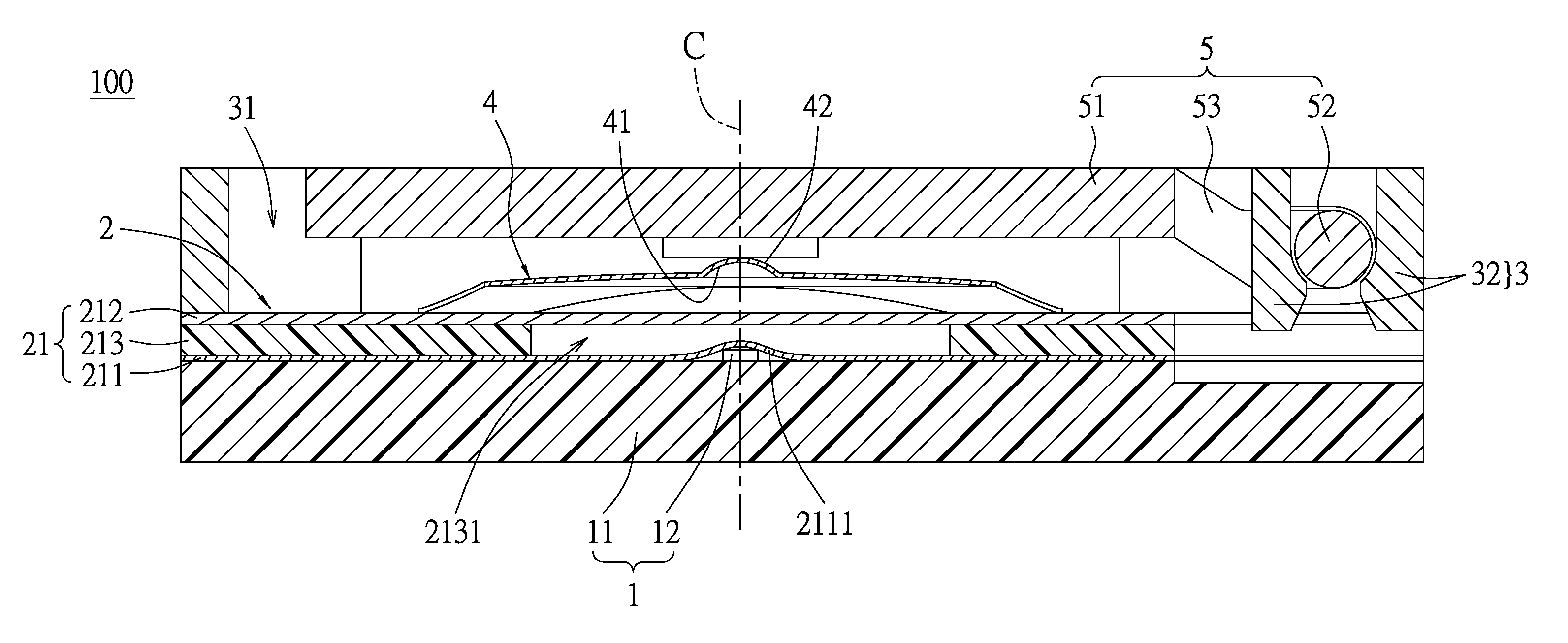
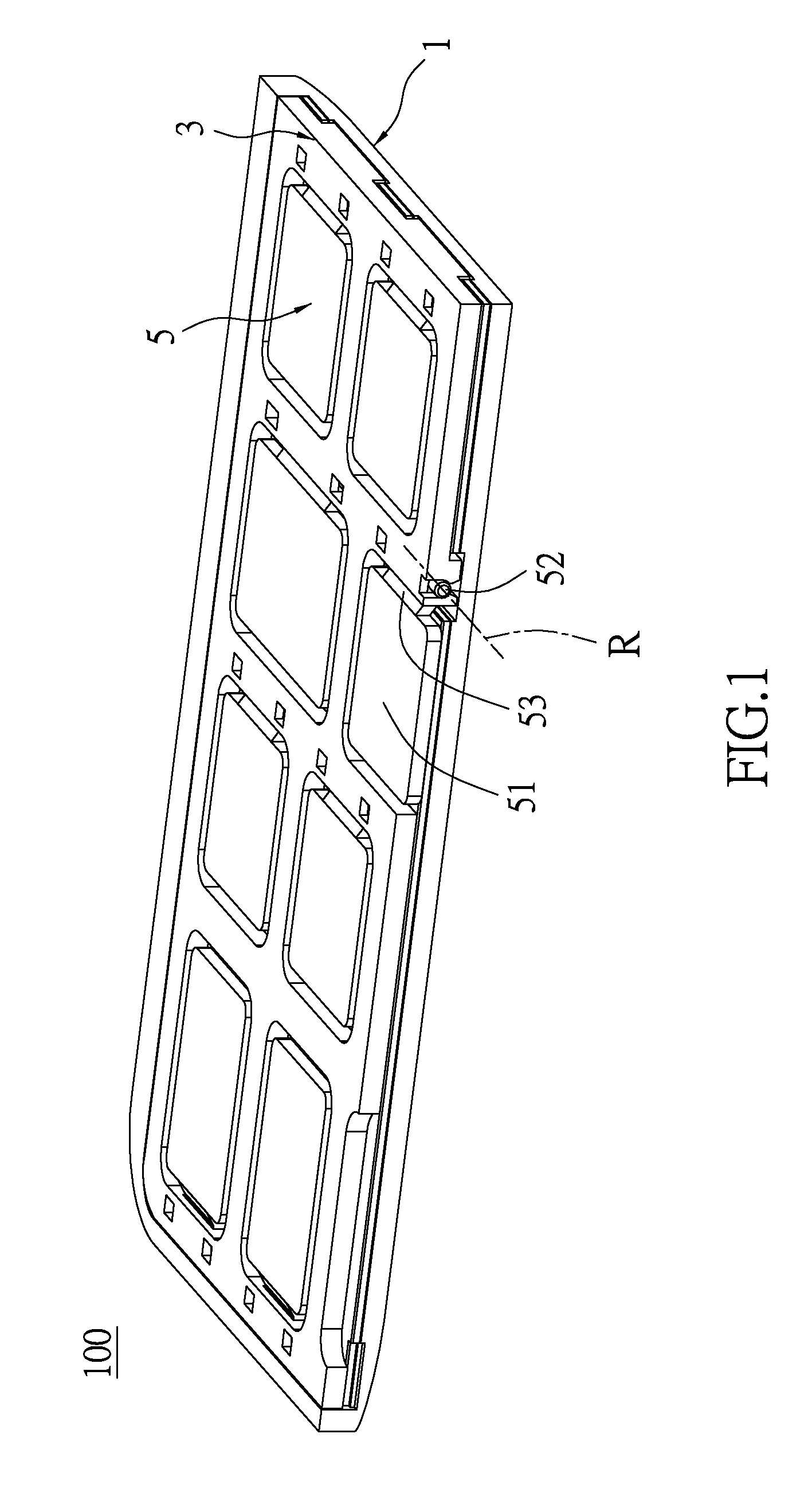
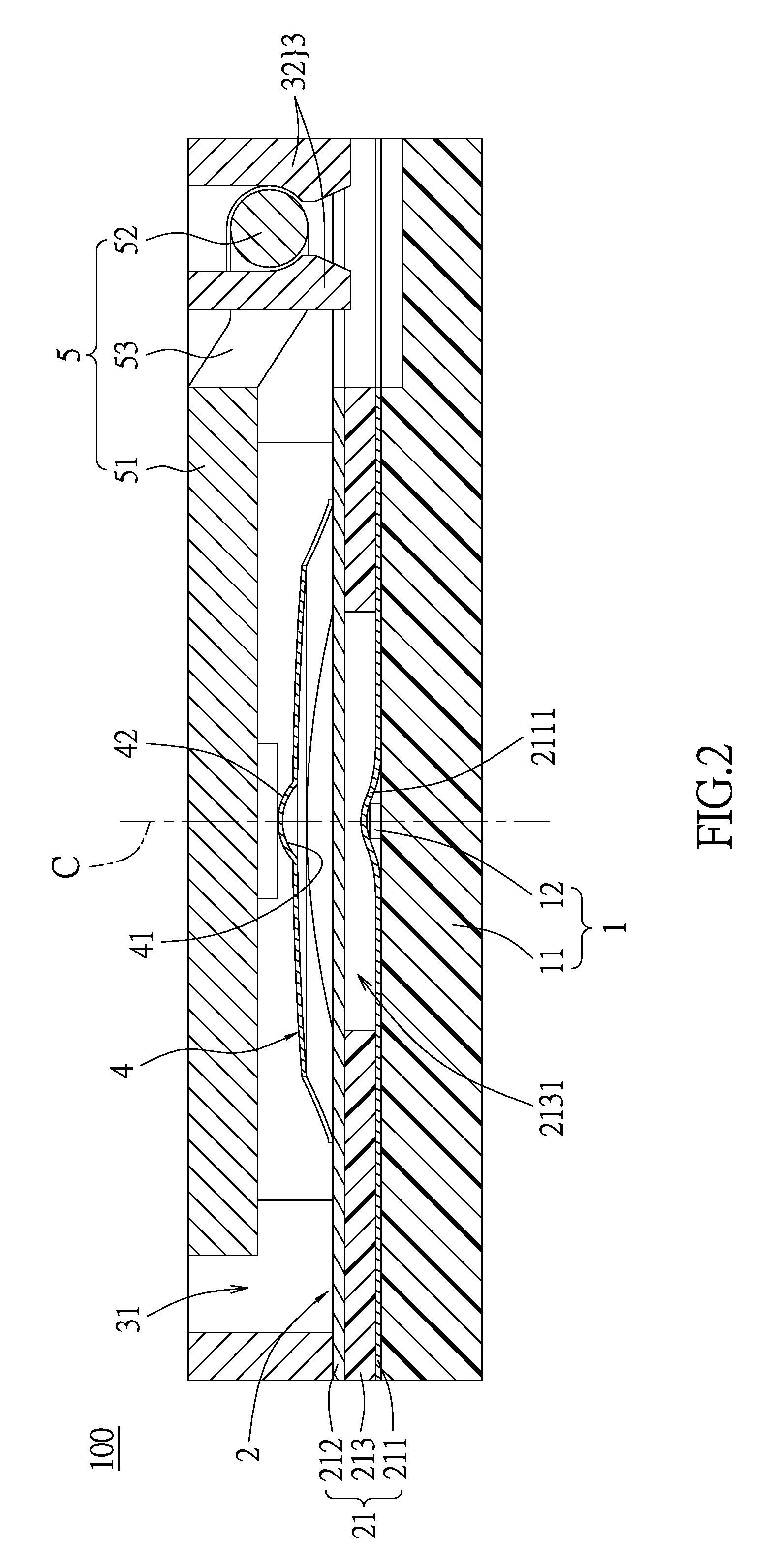
[0033]Please refer to FIGS. 1 through 3, which show a first embodiment of the instant disclosure. The instant embodiment provides a thin key structure 100 having a supporting module 1, a circuit module 2, a frame 3, a metal dome 4, and a pressable module 5. The thickness of the thin structure 100 in the instant embodiment is preferable less than 3.4 mm. The following description states each element firstly, and then states the relationship between the elements at an appropriate time.

[0034]The supporting module 1 has supporting plate 11 resembling a plane and a protrusion 12 disposed on the supporting plate 11. The supporting plate 11 has a plane defined therein. The plane defines a central axis C perpendicular thereto, and the protrusion 12 is arranged on the central axis C.

[0035]The instant embodiment takes the protrusion 12 installed on the supporting plate 11 as an example, that is to say, the protrusion 12 is an independent element (e.g., block). The protrusion 12 can be formed ...

second embodiment

[0049]Please refer to FIGS. 7 through 9, which show a second embodiment of the instant disclosure. The instant embodiment is similar to the first embodiment, and the identical features are not state again. The difference between the instant embodiment and the first embodiment is the frame 3 and the pressable module 5. The frame 3 of the instant embodiment does not have the pivoting portion 32, and the pressable module 5 of the instant embodiment is stated as follows.

[0050]The pressable module 5 has a key body 51 and a positioning sheet 54. The positioning sheet 54 has an assembling portion 52 and a connecting portion 53 formed thereon. Specifically, the positioning sheet 54 in the instant embodiment has at least one U-shaped opening. A portion of the positioning sheet 54 surrounded by the U-shaped opening is defined as the connecting portion 53, and the other portion of the positioning sheet 54 is defined as the assembling portion 52. A segment of the assembling portion 52 adjacent ...

third embodiment

[0056]Please refer to FIGS. 15 through 17, which show a third embodiment of the instant disclosure. The instant embodiment is similar to the first embodiment, and the identical features are not state again. The difference between the instant embodiment and the first embodiment is the frame 3 and the pressable module 5. The frame 3 of the instant embodiment does not have the pivoting portion 32, but the frame 3 has a track unit 34 formed on an inner side thereof. The pressable module 5 and the track unit 34 of the instant embodiment are stated as follows.

[0057]The track unit 34 has a plurality of tracks 341. In more detail, the tracks 341 are formed on two opposite inner lateral walls of the frame 3, and each track 341 defines as a path parallel to the central axis C. Moreover, each track 341 has a stopper 3411 arranged on a portion of each track 341 away from the circuit module 2 to limit the path defined by each track 341, The track 341 is arranged between the circuit module 2 and ...


PUM


Abstract

A thin key structure includes a supporting module, a circuit module disposed on the supporting module, a frame and a metal dome disposed on the circuit module, a pressable module, and a guiding portion. The supporting module has a supporting plate and a protrusion disposed on the supporting plate. The supporting plate has a plane defined therein, the plane defines a perpendicular central axis, and the protrusion is arranged on the central axis. The circuit module has a protruding segment formed by the protrusion. The metal dome is arranged in the frame, and has a contact portion arranged on the central axis. The guiding portion arranged on the central axis and is disposed between the contact portion and the pressable module. The metal dome is pressed by the guiding portion to move the contact portion along the central axis and selectively abuts the circuit module.

Description

BACKGROUND OF THE INVENTION[0001]1. Field of the Invention[0002]The instant disclosure relates to a key structure; more particular, to a thin key structure.[0003]2. Description of Related Art[0004]The key structure is a common input device, which is widely used in different electronic devices, such as the mobile phones, the handheld computers, and the remote controllers. Currently, with the miniaturization of the various electronic devices, the thickness of the key structure is designed toward thinner and thinner. However, the conventional key structure still has some problems, which need to be overcome.[0005]For example, the conventional key structure mainly has a key, an elastic layer, and a circuit board. The elastic layer is disposed under the key, and is disposed on the circuit board, and the elastic layer has an elastic sheet arranged correspondingly to the key. Thus, when the key is pressed down, the center portion of the elastic sheet is elastically concaved, so that the con...

Claims


Application Information

Patent Timeline
Patent Type & Authority Patents(United States)
IPC IPC(8): H01H13/702H01H13/705H01H13/7073
CPCH01H13/7073H01H2205/024H01H2215/006H01H2221/016H01H2227/036
Inventor LIU, CHANG-LICHANG, YU-CHIH
Owner ICHIA TECH
Why Eureka
Try Eureka