Hot filling system for bottles

a filling system and bottle technology, applied in the direction of filling without pressure, liquid handling, packaging goods, etc., can solve the problems of unfavorable thermal treatment cycle effectiveness, foam formation, and undesired level drop

Active Publication Date: 2015-08-18
SIPA SOCIETA INDUSTRIALIZZAZIONE PROGETTAZIONE E AUTOMAZIONE SPA
View PDF13 Cites 3 Cited by
  • Summary
  • Abstract
  • Description
  • Claims
  • Application Information

AI Technical Summary

Benefits of technology

[0020]It is an object of the present invention to provide a bottle filling valve which allow to meet all the requirements determined by the typical peculiarities of hot filling applications in the most effective manner possible, while allowing to maintain the same basic configuration also for cold processing plain liquids without recirculation needs, e.g. plain water.

Problems solved by technology

Furthermore, when the hot filling process is carried out using PET bottles, it has some particularities which require the solution of some specific problems.
A first problem to be solved consists in heating each filling valve along with the filling system before starting the filling process to avoid the product from cooling down, which would compromise the effectiveness of the thermal treatment cycle.
A second problem to be solved is that of upturning the bottle for a few seconds immediately after closing the cap in order to make the beverage, which is still hot, lap on the internal surfaces of the cap and neck of the bottle which emerge from the liquid, the so-called “head space”, thus subjecting them to a thermal treatment which is the more effective the smaller the extension of such surfaces.
For this reason, a high level is normally required in the bottle after filling, which level is often not reachable by the deflection systems of the prior art.
A third problem is related to the fact that the filling process of several products, particularly at high temperature, tends to cause the formation of foam.
Such a foam should be removed before capping because it will dissolve once the container has been closed, thus causing an undesired lowering of the level.
Another problem is that during extended machine stops, the step of in-valve recirculation should be activated both to avoid the system from cooling down, in particular the product close to the closed valves waiting for being bottled, and the step of in-bottle recirculating to avoid the product in the previously filled bottles from cooling down before capping, which event would cause the bottles to be rejected.
In the frequent case of bottles with a small diameter neck, the passing section made available for filling and for evacuating foams is limited.
a) they further reduce the active sections thus requiring a certain thrust, i.e. the piezo load, which causes undesired strains on the plastic bottle,
b) they do not allow an optimal deflection which generates foam,
c) they do not allow rapid foam evacuation, which causes a high percentage of recirculating product,
d) they penetrate into the bottle and remain submerged in the liquid at the end of filling, whereby the level decreases when the beak is extracted, which is an undesirable effect.
Another important problem is that the market increasingly requires more 100% fruit juice or fruit-based beverages containing a given amount of pulps, filaments or cells which confer particular features of “naturalness” to the beverage.
The presence of pulps in the beverage is detrimental to the recirculation control systems traditionally based on calibrated orifices.
Furthermore, if the filling process causes excessive turbulence, the pulp tends to incorporate an amount of foam which does not rapidly rise to the surface and which may be removed only by means of a very long step of recirculating which causes, as mentioned above, a large amount of recovered product and a deterioration of the organoleptic features of the product.
When the solution of making the nozzles and deflection systems penetrate into the bottle is used in order to optimize the foodstuff flow, these being partially submerged in the liquid at the end of filling to then emerge during the step of detaching from the bottle, problems of product spillage may easily occur, with consequent fouling of the mouth exterior and subsequent formation of mould in the gaps between capsule and bottle, or particularly in the case of small diameter necks, problems of final level lowering caused by the emersion of these parts may occur.

Method used


Image

  • Hot filling system for bottles
  • Hot filling system for bottles
  • Hot filling system for bottles

Examples


first embodiment

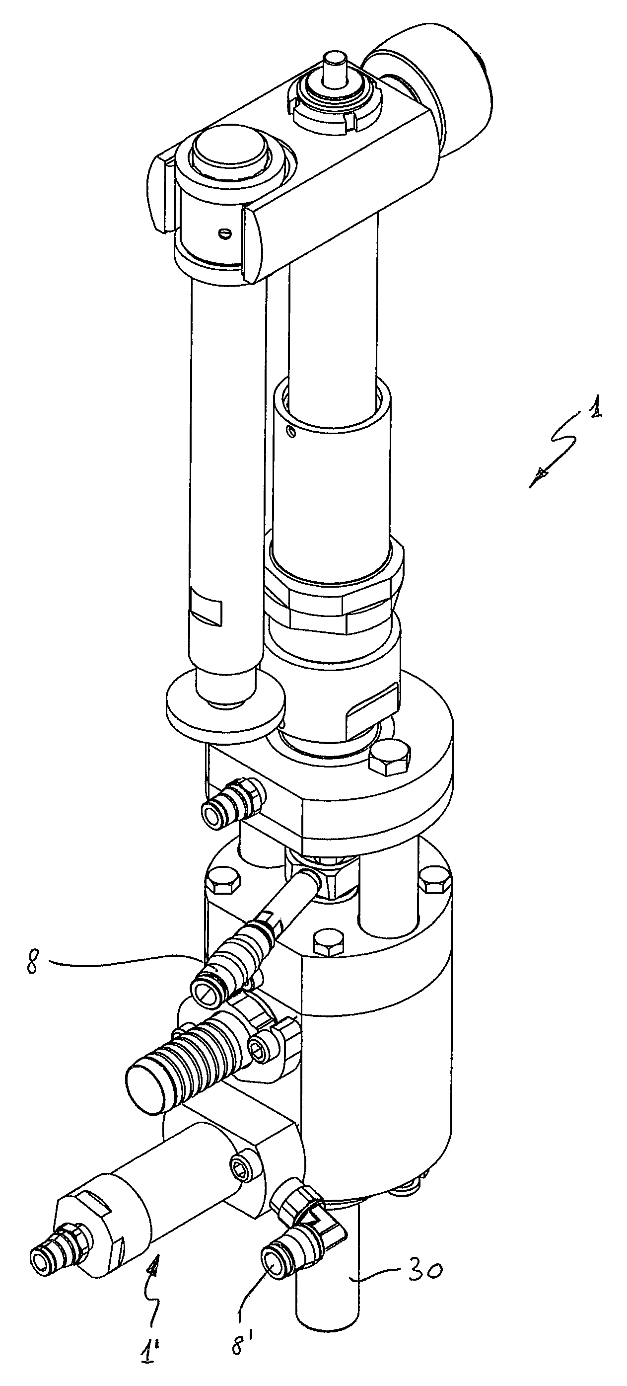
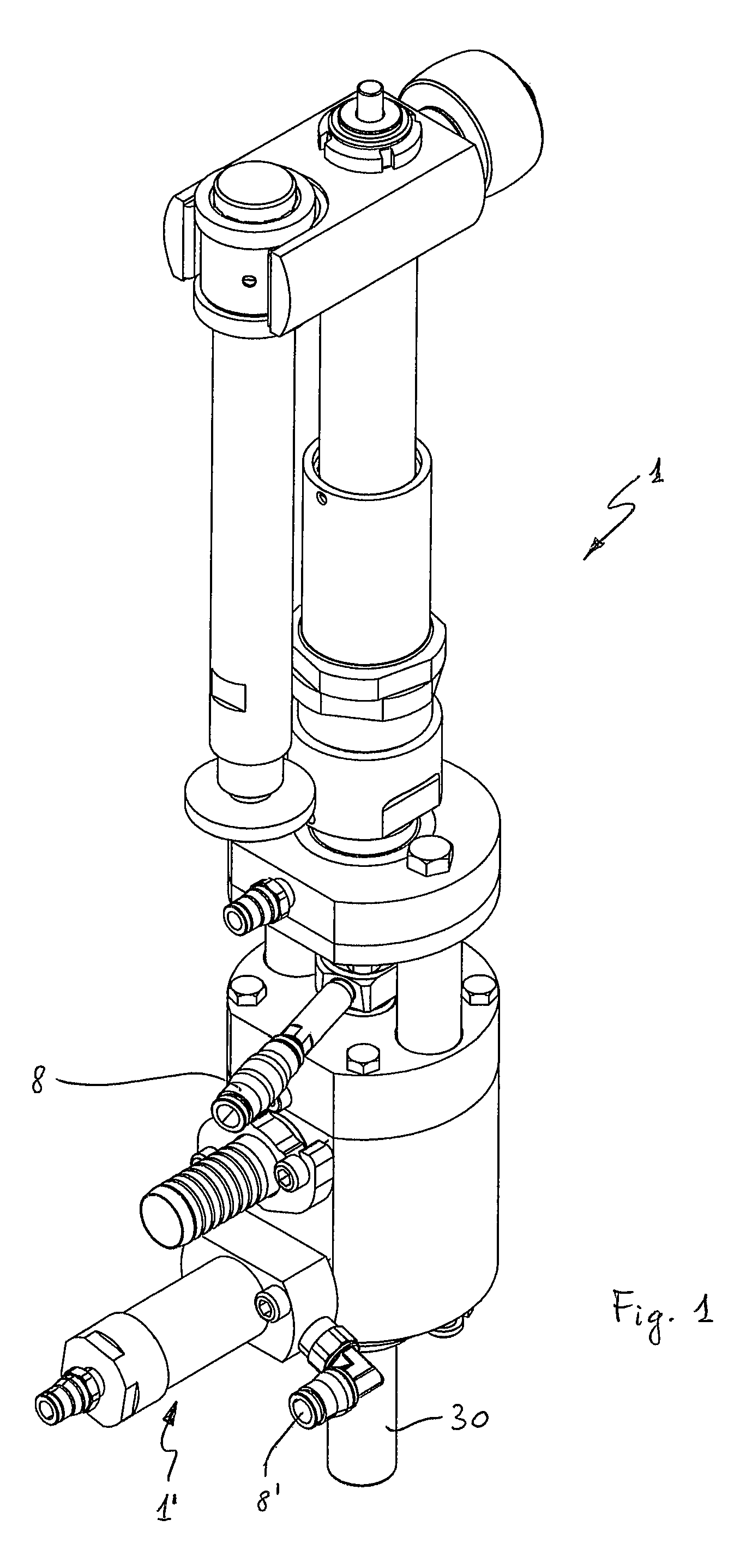
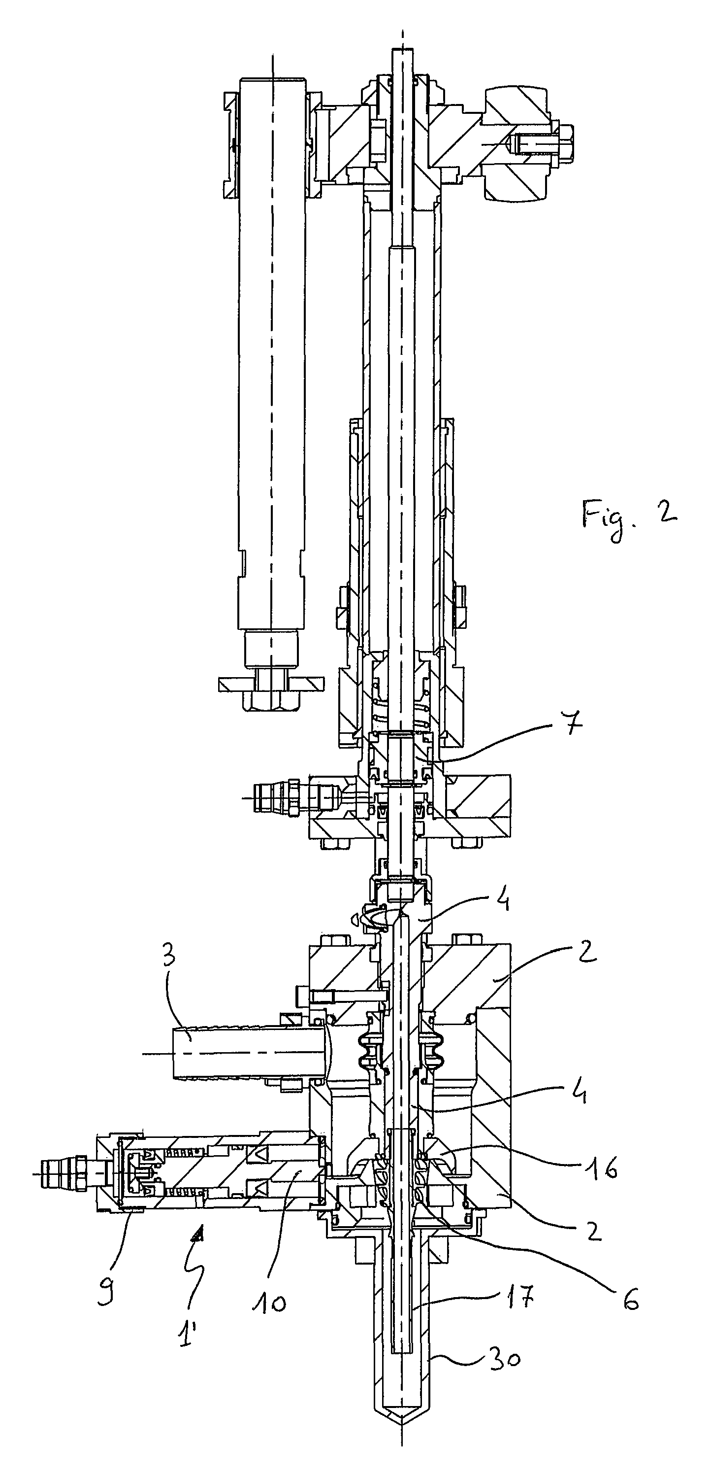
[0073]In a first embodiment, the conical configuration of the swirler 6 inside a conical, frustoconical or frustoconocal-cylindrical hole, i.e. constituted by a first frustoconical part followed in the vertical direction by a second cylindrical part (FIG. 5), allows to increase the available passage section for the product when the main shutter 4 of the valve opens, thus minimizing the likelihood of obstruction due to the passage of pulps contained in the liquid.

second embodiment

[0074]In a second embodiment, the cylindrical configuration of the swirler 6 inside a cylindrical hole (FIG. 6) is useful in that the swirler may be disassembled from the valve by removing it from the bottom, by simply unscrewing the tubular element or beak 17 on which it is mounted. In the case of clear products, this allows to mount a beak with a traditional deflector, if the machine needs to also process cold products at a higher output speed, provided that the product level in the bottle allows this circumstance.

third embodiment

[0075]In a third embodiment, the conical configuration of the swirler 6 inside a cylindrical hole (FIG. 6d) has the same advantage of the cylindrical configuration of the swirler inside a cylindrical hole, with the further advantage of reducing to minimum the likelihood of jamming because pulps or filaments that are stuck can free themselves more easily.

[0076]Furthermore, the position of the swirler directly in contact with the lower end of shutter 4 above avoid pulps, cells or filaments from remaining astride the crests of the helixes, finding no horizontal surface with which to get caught. While maintaining the efficiency of the systems traditionally applied to the filling of clear juices, the aforesaid conformation of the deflection system advantageously allows beverages with a high content of pulps and filaments to pass through.

[0077]The helixes of swirler 6 are advantageously dimensioned so that the helical pipes 13 are such to pass pulps of maximum size contained in the produc...


PUM

PropertyMeasurementUnit
kinematic viscosityaaaaaaaaaa
internal diameteraaaaaaaaaa

Abstract

A filling valve (1) for hot filling plastic bottles, which allows to meet all the requirements determined by the typical particularities of hot filling applications in the most effective manner possible, while allowing to maintain the same basic configuration also for cold processing plain liquids without needing recirculation, e.g. plain water. The filing valve (1) comprises:—a valve body (2) defining therein a space for the passage of a filing liquid and provided with a hole for introducing said liquid in one of said containers,—a first shutter (4) of said hole, sliding within the valve body (2), a siphon (5) between said space and said hole, and a liquid deflection element (6) accommodated in said hole, configured so as to confer a rotational component to the liquid which crosses it, which permits the liquid itself to adhere to the walls of the container during the step of filing, said deflection element (6) being integrally fixed to and directly in contact with said first end of the first shutter (4).

Description

FIELD OF THE INVENTION[0001]The present invention relates to a bottle filling valve, particularly adapted to hot fill plastic bottles with alimentary liquids, such as fruit juice, isotonic beverages, milk and other similar beverages, and to a corresponding system comprising a plurality of filling valves.STATE OF THE ART[0002]In order to ensure the preservation and safety of beverages or, in general, of foodstuff in the liquid form subjected to microbiological deterioration, such as milk, wine, beer, juice, tea, etc., a pasteurization process is generally applied, which consists in heating the foodstuff in order to reduce or suppress the presence of certain microorganisms. In the case of fruit juice, tea or isotonic beverages, one of the most common methods for avoiding the pasteurized beverage from being contaminated again before packaging is to fill the containers while maintaining the beverage itself over a certain temperature. Such a temperature depends on the type of product and...

Claims


Application Information

Patent Timeline
Patent Type & Authority Patents(United States)
IPC IPC(8): B65B1/30B67C3/28B67C3/04B67C3/26
CPCB67C3/045B67C3/281B67C2003/2671
Inventor MAURO, PASQUALEABATI, STEFANOZOPPAS, MATTEO
Owner SIPA SOCIETA INDUSTRIALIZZAZIONE PROGETTAZIONE E AUTOMAZIONE SPA
Why Eureka
Try Eureka