Rolling bearing unit

a technology of rolling bearings and units, which is applied in the direction of bearing cooling, rolling contact bearings, shafts and bearings, etc., can solve the problems of unsatisfactory bearing lubricating performance and adverse bearing lubrication effects

Inactive Publication Date: 2015-08-18
JTEKT CORP
View PDF10 Cites 140 Cited by
  • Summary
  • Abstract
  • Description
  • Claims
  • Application Information

AI Technical Summary

Benefits of technology

[0008]A rolling bearing unit according to an aspect of the invention includes: a rolling bearing having an inner ring arranged on a rotary shaft, an outer ring arranged on an inner peripheral face of a housing, a plurality of rolling elements rollably arranged in an annular space between the inner ring and the outer ring, and a cage that holds the rolling elements; and a cage guide member that is formed integrally with the outer ring or formed as a member different from the outer ring, that is fixed to the housing, and that has a guide face that guides an inner peripheral face of the cage while supplying grease. The cage guide member has a guide projection projected into the annular space and having an outer peripheral face a part of which serves as the guide face, and a grease supply portion having a grease reservoir portion in which the grease is reserved, and a supply port through which the grease is supplied from the grease reservoir portion to the guide face and which is formed on the outer peripheral face of the guide projection, at a position closer to a base end portion of the guide projection than the guide face.

Problems solved by technology

In this case, there is a possibility that the base oil will not be supplied to the raceway surface, causing adverse effects on lubrication of the bearing.
However, when the influence of the cooling system is exerted from the housing on the bearing fitted to the rotary shaft, separation of the base oil from the grease is further less likely to occur, causing a possibility that satisfactory bearing lubricating performance will not be ensured.

Method used


Image

  • Rolling bearing unit
  • Rolling bearing unit
  • Rolling bearing unit

Examples


first embodiment

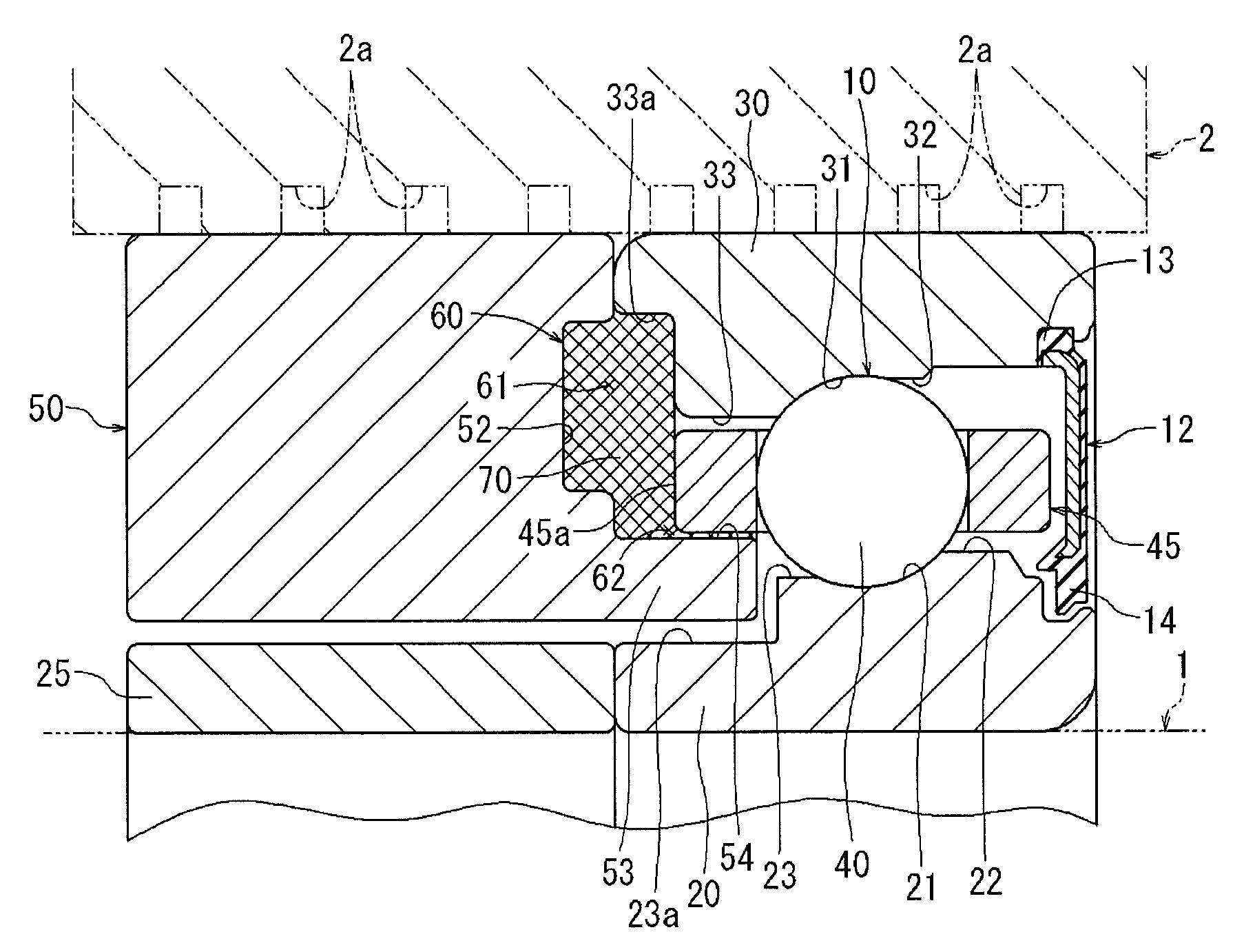
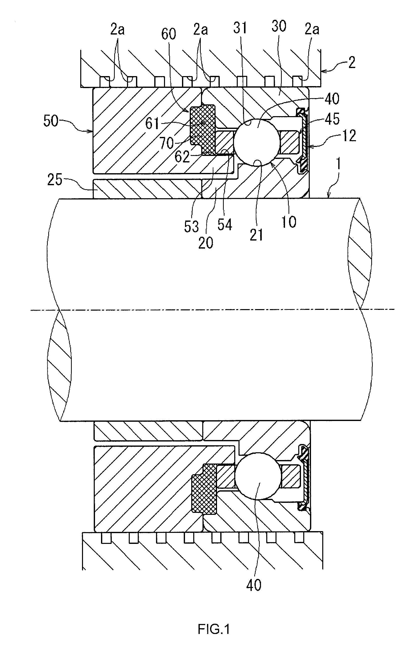
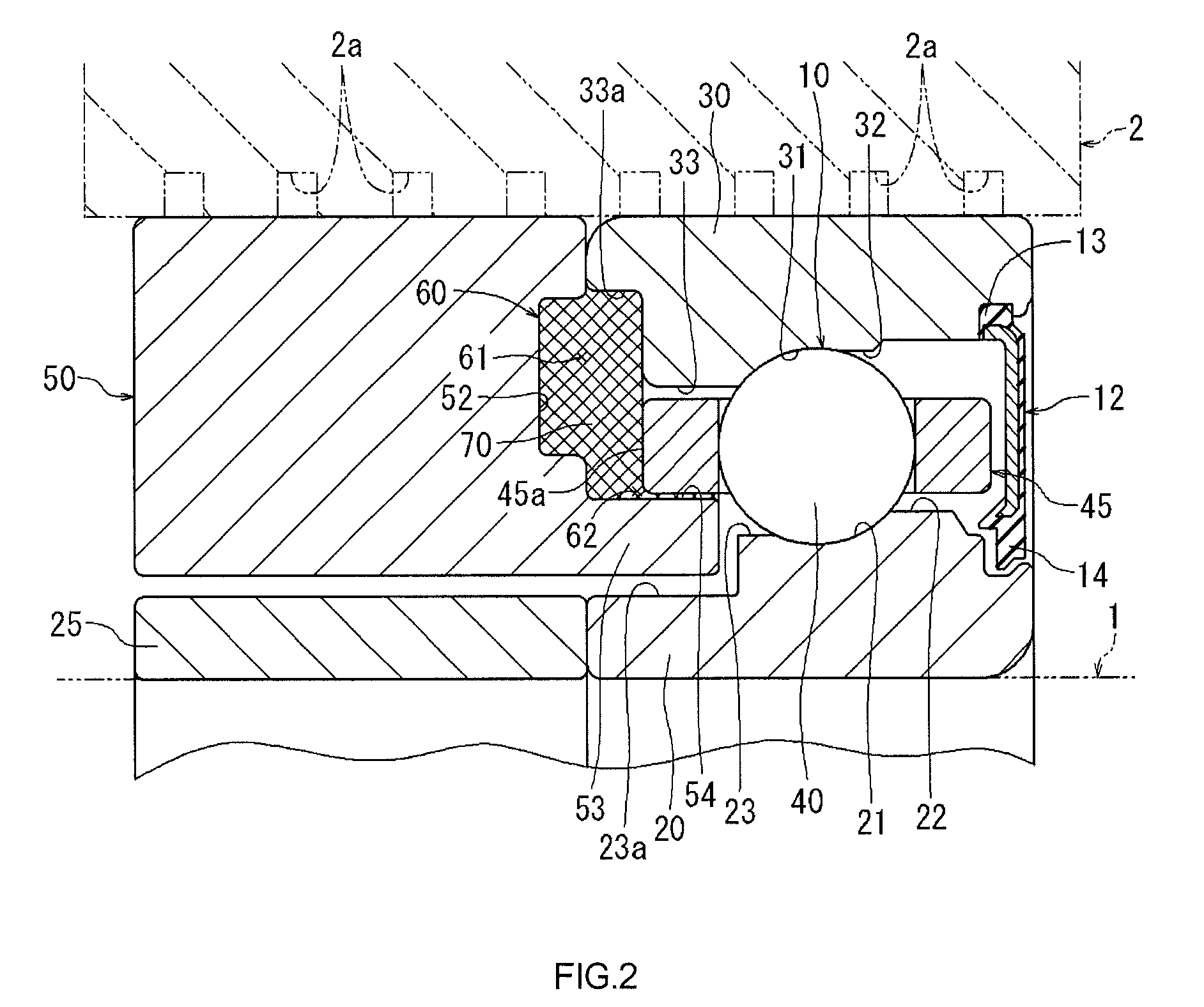
[0016]As illustrated in FIG. 1, the outer ring 30 is formed into a cylindrical shape, and is arranged on the same central axis as that of the inner ring 20. The outer ring 30 is arranged radially outward of the inner ring 20 across an annular space. The outer ring 30 has an outer peripheral face that is fixedly fitted to a housing 2. As illustrated in FIG. 2, an outer ring raceway surface 31 is formed in substantially the axially center portion of the inner peripheral face of the outer ring 30, and raceway shoulder portion portions 32, 33 are formed on respective sides of the outer ring raceway surface 31. In the first embodiment, the raceway shoulder portion 32 located on the right side in FIG. 2 has an inner peripheral face of which the inner diameter is greater than that of an inner peripheral face of the raceway shoulder portion 33 located on the left side in FIG. 2. A stepped portion 33a having an inner diameter that is larger, by an appropriate amount, than that of the raceway...

second embodiment

[0027]In the thus configured rolling bearing unit in the second embodiment, the cage 45 is restrained from tilting by the guide faces 54 that are formed on the outer peripheral faces of the guide projections 53 of the cage guide members 50, and therefore rotation of the cage 45 is guided more stably. The grease 70 is reserved in the two grease reservoir portions 61. Therefore, the base oil of the grease 70 in the two grease reservoir portion 61 is reliably supplied to the spaces between the guide faces 54 and the inner peripheral face of the cage 45.

[0028]Note that the invention is not limited to the first embodiment and the second embodiment, and may be implemented in various other embodiments within the scope of the invention. For example, in the first and second embodiments, the grease reservoir portion 61 is formed of the space surrounded by cage guide member 50, the outer ring 30 and the axial end face 45a of the cage 45. Alternatively, the invention may be implemented if the g...


PUM


Abstract

A rolling bearing unit includes: a rolling bearing having an inner ring, an outer ring arranged, multiple rolling elements, and a cage; and a cage guide member that is formed integrally with the outer ring or formed as a member different from the outer ring, and that is fixed to the housing side. The cage guide member has a guide projection projected into an annular space between the inner and outer rings and having an outer peripheral face a part of which serves as the guide face, and a grease supply portion having a grease reservoir portion in which the grease is reserved. A supply port through which the grease is supplied from the grease reservoir portion to the guide face is formed on the outer peripheral face of the guide projection, at a position closer to a base end portion of the guide projection than the guide face.

Description

INCORPORATION BY REFERENCE[0001]The disclosure of Japanese Patent Application No. 2013-004501 filed on Jan. 15, 2013 including the specification, drawings and abstract is incorporated herein by reference in its entirety.BACKGROUND OF THE INVENTION[0002]1. Field of the Invention[0003]The invention relates to a rolling bearing unit including a rolling bearing and a grease supply portion that supplies grease to the rolling bearing.[0004]2. Description of Related Art[0005]A rolling bearing unit including a rolling bearing and a grease supply portion that supplies grease to the rolling bearing is described in, for example, Japanese Patent Application Publication No. 2011-58520 (JP 2011-58520 A). In the rolling bearing unit, an annular grease reservoir forming member in which a grease reservoir is formed is arranged radially inward of a spacer located adjacent to an outer ring of the rolling bearing. The grease reservoir forming member has a clearance forming piece having a distal end fac...

Claims


Application Information

Patent Timeline
Patent Type & Authority Patents(United States)
IPC IPC(8): F16C33/46F16C33/60F16C33/58F16C33/66F16C37/00
CPCF16C33/6611F16C33/6614F16C33/6648F16C33/6651F16C37/007F16C33/586F16C33/605F16C33/6629F16C33/6681F16C19/163
Inventor MISADA, YASUHARU
Owner JTEKT CORP
Why Eureka
Try Eureka