Shut-off valve

a technology of shut-off valve and valve body, which is applied in the direction of lift valve, valve details, engine components, etc., can solve the problem of not always being able to guaran

Active Publication Date: 2015-08-18
SURESTOP
View PDF7 Cites 2 Cited by
  • Summary
  • Abstract
  • Description
  • Claims
  • Application Information

AI Technical Summary

Benefits of technology

[0010]It is an object of the present invention to provide an improved shut-off valve, and in particular a shut-off valve which can replace the stop-cock if desired.
[0015]Preferably the control member includes a compression spring. Desirably, the compression spring lies between the valve member and a post. The use of a compression spring broadens the tolerance ranges for the post and other parts of the control member.
[0021]The mechanical force with which the control member holds the valve member against the valve seat can avoid any tendency of the diaphragm valve to open if the differential pressure falls close to zero, and can in some embodiments maintain the diaphragm valve closed in the presence of back-pressures (i.e. the pressure at the outlet being greater than the pressure at the inlet).

Problems solved by technology

Prior art shut-off valves such as that of EP 1 195 547 cannot usually replace the stop-cock since it is not possible to guarantee that the water flow will be prevented when the shut-off valve is closed.
It is not always possible to guarantee that the pressure at the inlet will exceed the pressure at the outlet by at least this threshold value, especially with a mains water supply to a domestic dwelling, and so the shut-off valves are usually used in addition to (and typically downstream of) the stop-cock.

Method used


Image

  • Shut-off valve
  • Shut-off valve
  • Shut-off valve

Examples


Embodiment Construction

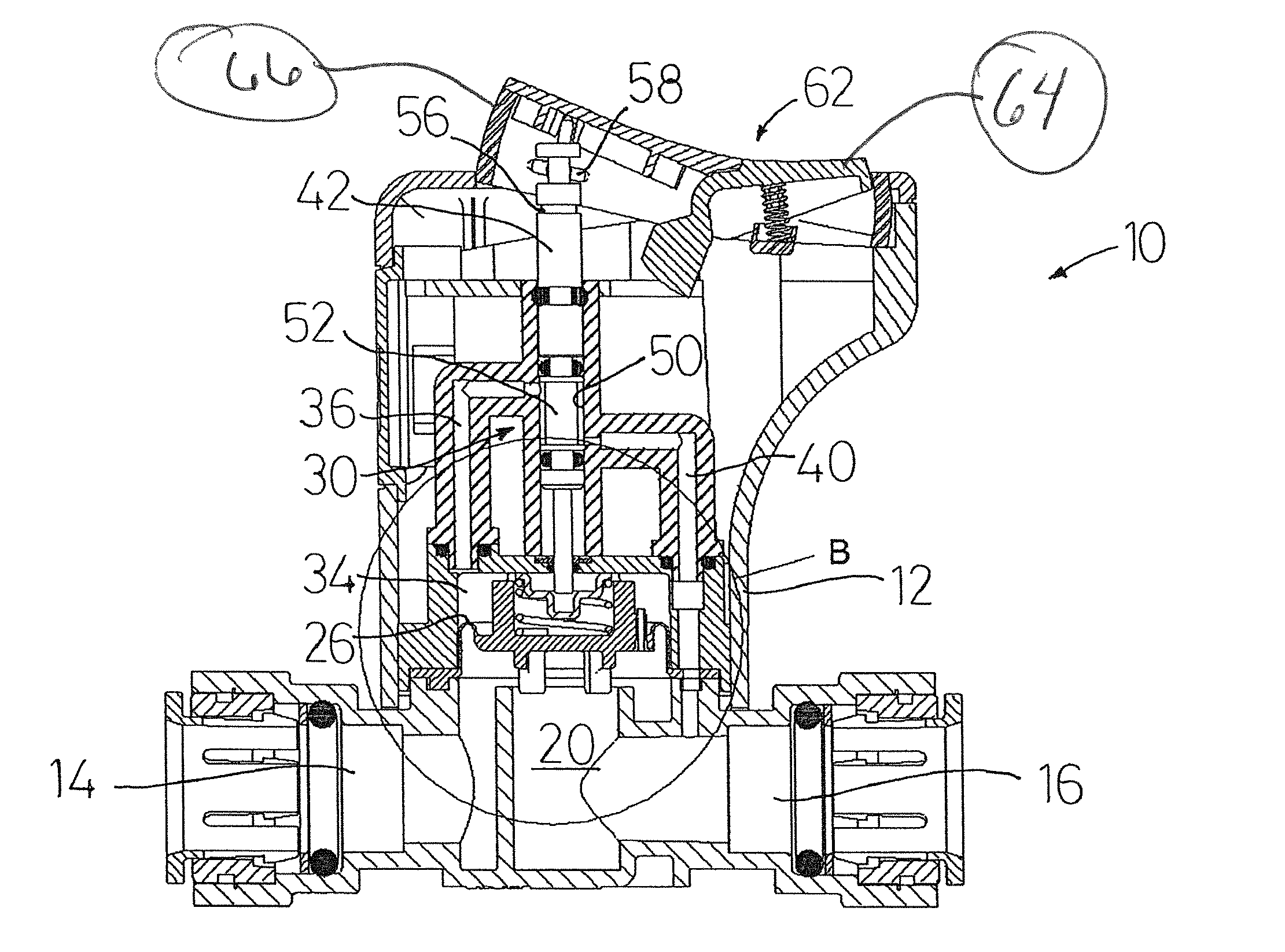
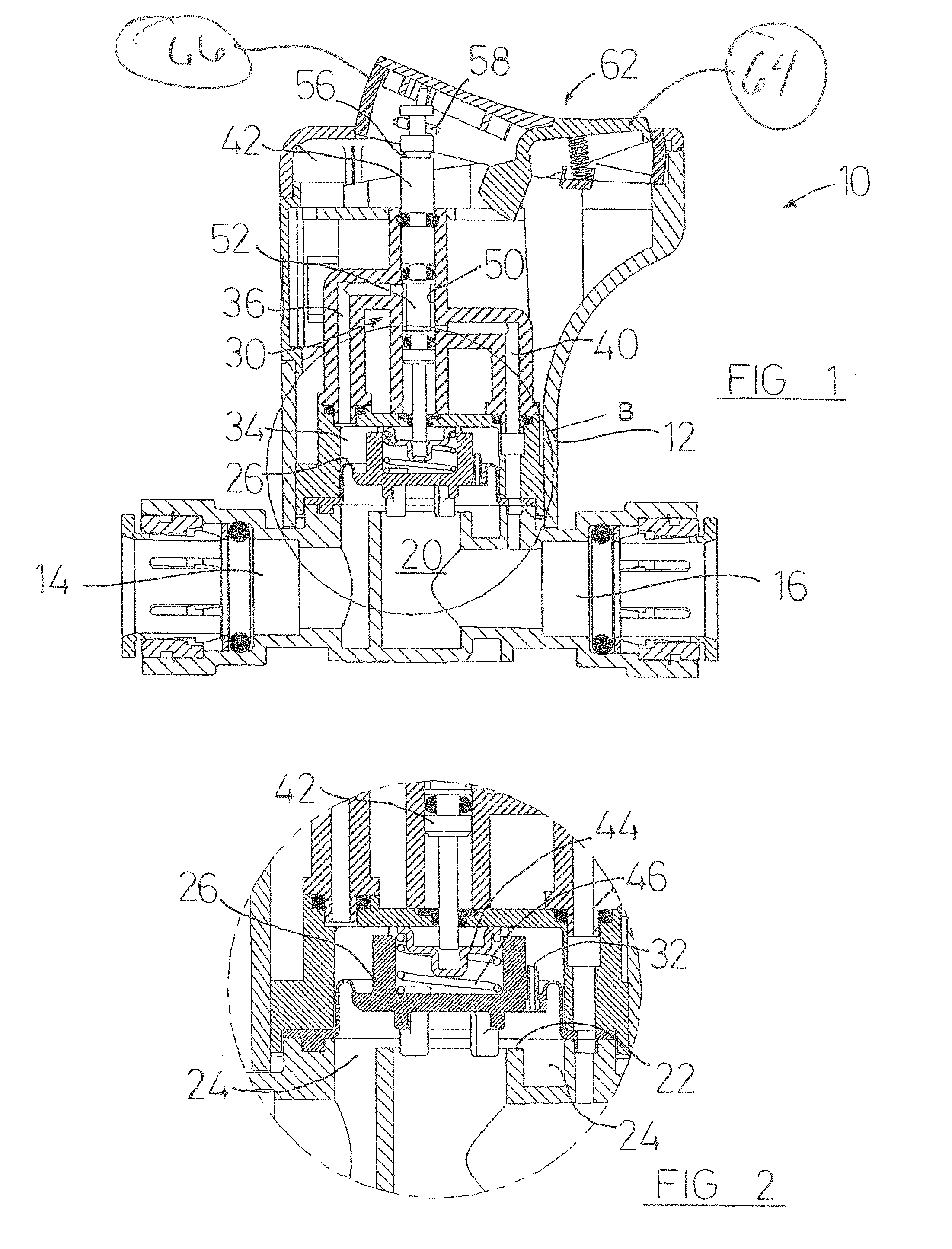
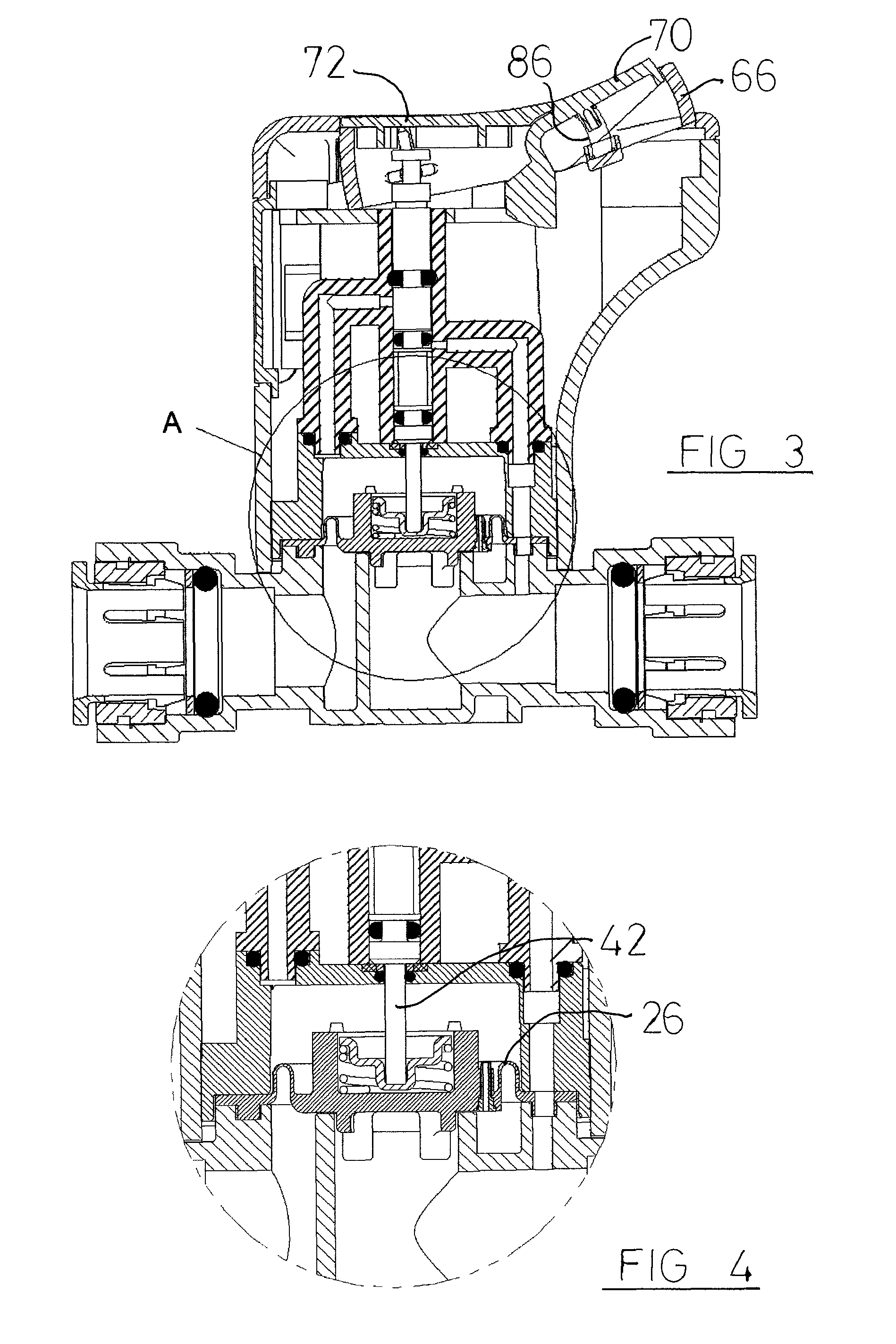
[0031]FIGS. 1-4 show a shut-off valve 10 according to the present invention. The shut-off valve 10 includes a diaphragm valve having a body 12, which in common with prior art diaphragm valves has an inlet 14 and an outlet 16. The outlet 16 is in fluid communication with the hollow interior 20 of the valve seat 22, and the inlet 14 is in fluid communication with the chamber 24 surrounding the valve seat 22.

[0032]The valve member or diaphragm 26 is secured to the body 12, and is flexible so that it can alternately seal against the valve seat 22, in which case it closes off the flow of fluid from the chamber 24 to the hollow interior 20 (and so from the inlet 14 to the outlet 16), and be free of the valve seat, in which case fluid can flow from the chamber 24 to the hollow interior 20 (and so from the inlet 14 to the outlet 16).

[0033]The diaphragm valve of this embodiment shares many features of prior art diaphragm valves, as will be described here for ease of reference.

[0034]The posit...


PUM


Abstract

This invention relates to a shut-off valve, and primarily to a valve for shutting-off the flow of a fluid such as a mains water supply to commercial premises or a domestic dwelling. The shut-off valve (10) comprises a diaphragm valve and a pilot valve (30). The diaphragm valve has an inlet (14) and an outlet (16), a valve member (26) and a valve seat (22), the valve member having a closed position in which it engages the seat and prevents the flow of fluid from the inlet to the outlet, and an open position in which the valve member does not engage the seat and fluid can flow from the inlet to the outlet. A first fluid conduit (36) connects the inlet of the diaphragm valve to the inlet of the pilot valve, and a second fluid conduit (40) connects the outlet of the pilot valve to the outlet of the diaphragm valve. The pilot valve has an open position in which fluid can flow from the first fluid conduit to the second fluid conduit and a closed position in which fluid cannot flow from the first fluid conduit to the second fluid conduit. The invention is characterized in that the diaphragm valve has a control member (42, 44, 46) which is adapted to hold the valve member against the valve seat, whereby the diaphragm valve remains closed even if the pressure at its outlet equals or perhaps exceeds the pressure at its inlet.

Description

FIELD OF THE INVENTION[0001]This invention relates to a shut-off valve, and in particular to a valve for shutting-off the flow of a fluid such as a mains water supply.[0002]The invention is expected to find its greatest utility as a shut-off valve for the water supply to a domestic dwelling, and the following description will therefore relate primarily to such application. However, use of the invention for other liquid flows such as liquid petrochemicals, and in other applications such as the water supply to commercial and recreational premises, are not thereby excluded. Also, the invention is applicable to gas flows, i.e. it can be used to shut off the flow of a gas along a pipeline.[0003]In this description, directional and orientational terms such as “up”, “down”, “lift” etc., refer to the valve in the orientation shown in FIGS. 1 and 3. For the avoidance of doubt, it will be understood that the valve may be used in other orientations, and the directional and orientational terms ...

Claims


Application Information

Patent Timeline
Patent Type & Authority Patents(United States)
IPC IPC(8): F01L3/10F16K31/385
CPCF16K31/385Y02A20/15
Inventor DALTON, MARTIN, WALTER
Owner SURESTOP
Why Eureka
Try Eureka