Wiper blade having an adapter unit for attaching to a wiper arm

a technology of adapter unit and wiper blade, which is applied in the field of wiper blade, can solve the problems of time-consuming and complicated mounting of wiper blade, complex manipulation of adapter unit, and inconvenient handling of various movement procedures, and achieves the effect of quick and reliable attachment, easy handling and convenient handling

Inactive Publication Date: 2015-08-25
ROBERT BOSCH GMBH
View PDF19 Cites 21 Cited by
  • Summary
  • Abstract
  • Description
  • Claims
  • Application Information

AI Technical Summary

Benefits of technology

[0005]It is therefore an aim of the invention to provide a new wiper blade for a windshield wiper having an adapter unit, which is easy to handle and can be quickly and reliably attached at a base connection device, which is provided on a wiper strip.
[0007]The invention therefore makes possible the provision of a wiper blade having an adapter unit which can be mounted in a simple way and which can be reliably and stably attached to the wiper blade.
[0009]A connection element can consequently be provided which can reliably be connected to the first and second adapter holder and can be easily separated again from them.
[0013]The invention therefore enables the provision of an adapter unit having a simple and uncomplicated construction.
[0015]The connection element can thus be disposed in a simple manner between the first and second adapter holder, wherein a positively locking connection between the adapter holders and said connection element can be established when the adapter holders and the connection element are appropriately configured.
[0017]An optically pleasing connection between the adapter holders and the wiper strip can therefore be achieved.

Problems solved by technology

A disadvantage of the prior art is that a combination of various movement procedures is required to attach the adapter unit at the base connection device of the wiper blade, i.e. initially a mounting at a specified angle, then a turning motion and finally a somewhat linear motion while applying a specified pressure.
The manipulation of the adapter unit is therefore difficult and the mounting of the wiper blade is time consuming and complicated.
Moreover, damage or destruction of individual components of the snap connection is, for example, possible should the adapter unit be canted on the base connection device as a result of the pressure required to achieve the linear motion.

Method used


Image

  • Wiper blade having an adapter unit for attaching to a wiper arm
  • Wiper blade having an adapter unit for attaching to a wiper arm
  • Wiper blade having an adapter unit for attaching to a wiper arm

Examples


Embodiment Construction

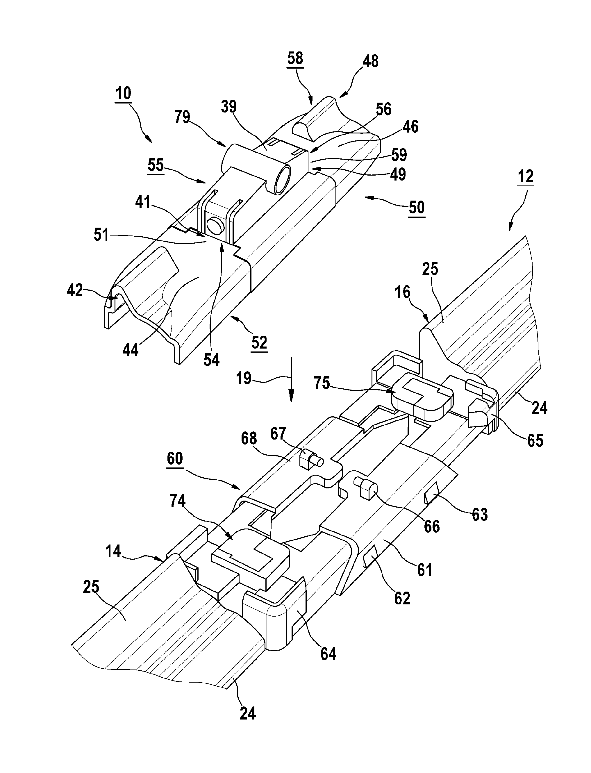
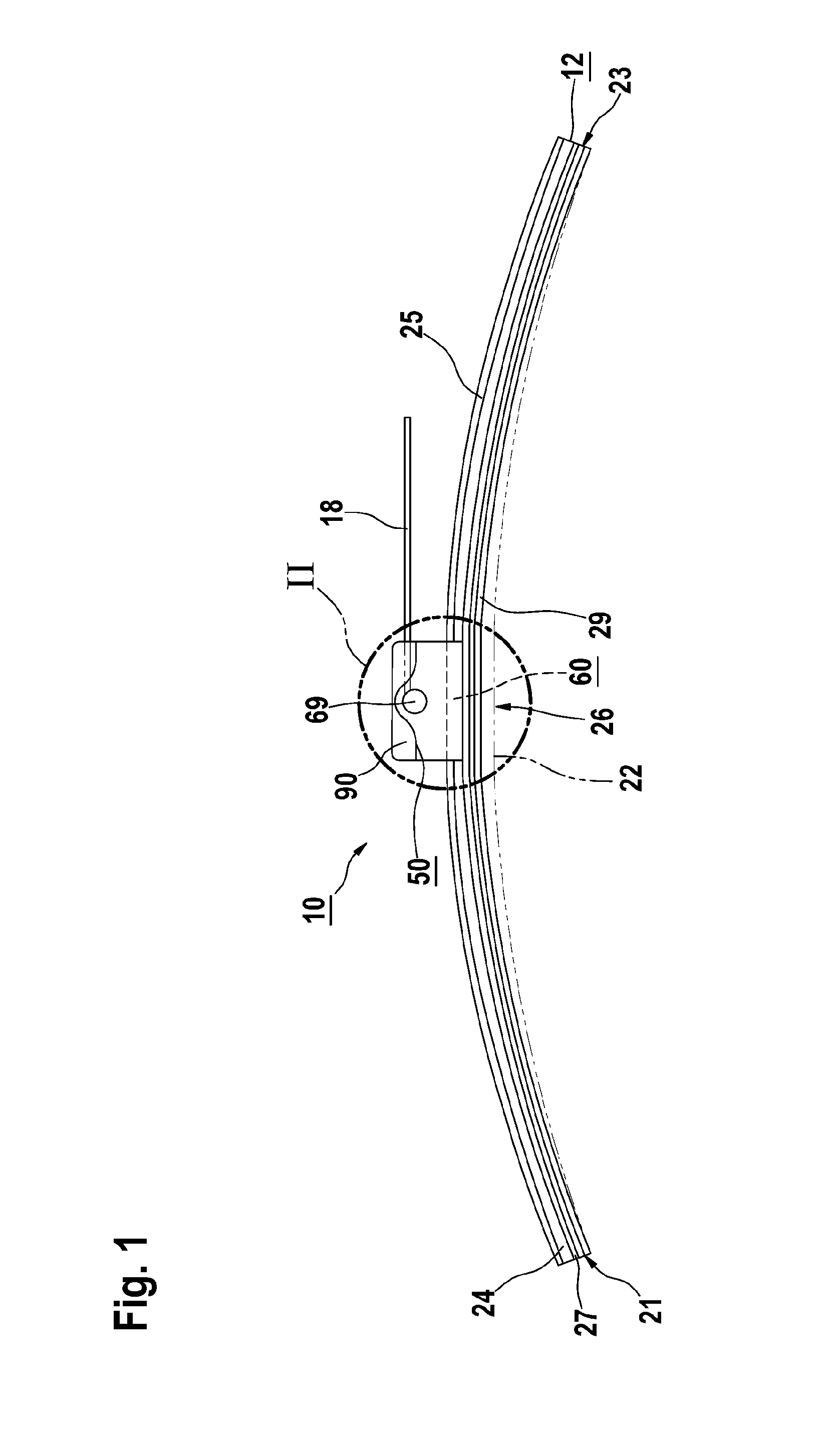
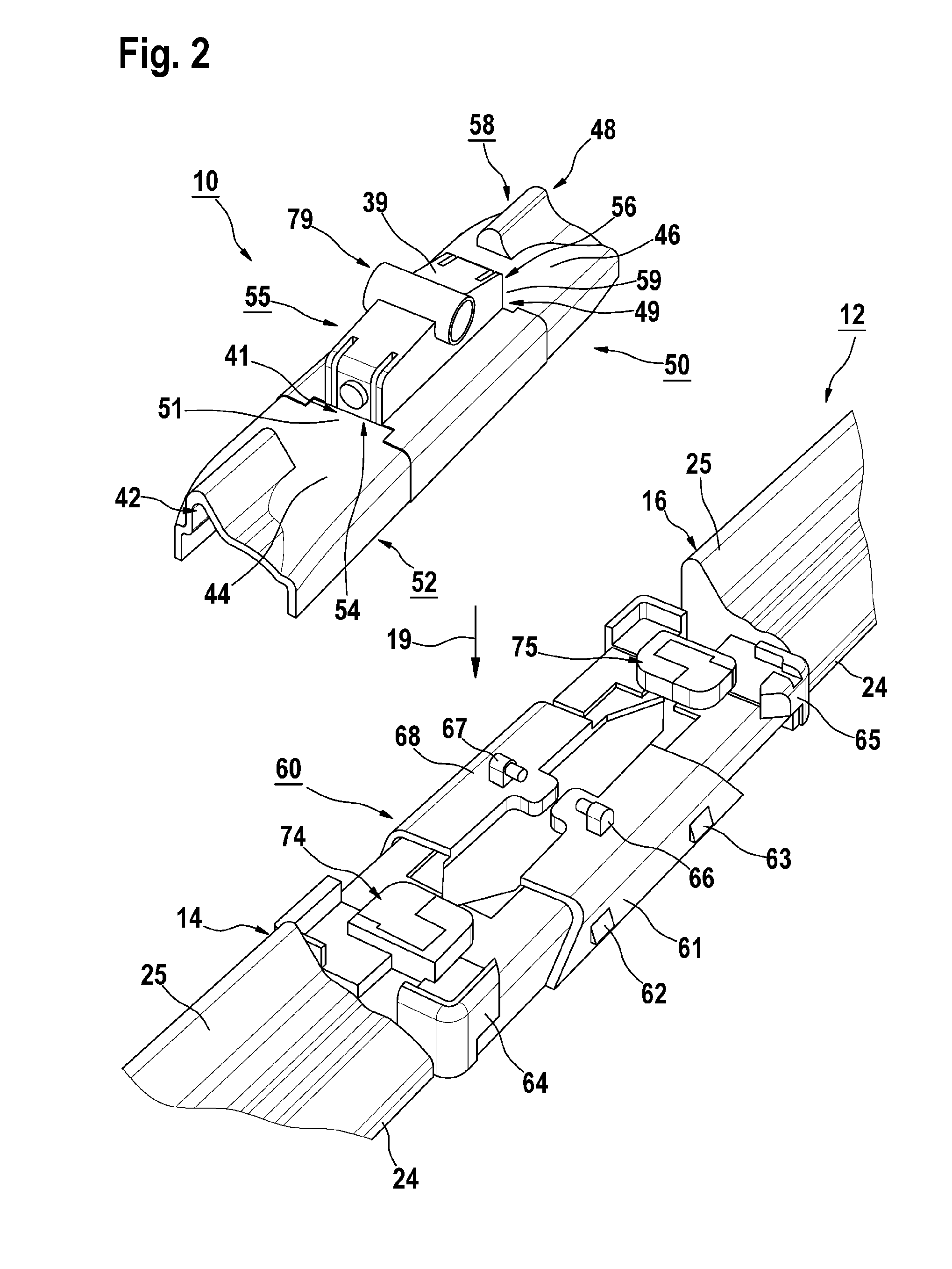
[0029]FIG. 1 shows a wiper blade 10 comprising a wiper strip 12, which has a wiper lip 29 which is connected to a back strip 24 via a swiveling web 27. A spoiler 25 is provided on the back strip 24. A base connection device 60, at which an adapter unit 50 for connecting a connecting member 90 provided on a wiper arm 18 is attached, is provided on the wiper strip 12. The connecting member 90 is connected by way of example to the adapter unit 50 via a pivot bolt 69. With the help of the wiper arm 18, the wiper blade 10 can be guided to wipe over the window pane 22 depicted with a dotdashed line, e.g. a motor vehicle window pane.

[0030]According to one embodiment, the wiper blade 10 is of flat bar design, i.e. the wiper strip 12 has lateral longitudinal grooves, in which two mounting rails, preferably spring rails, are disposed. Alternatively to this, said wiper strip 12 can be embodied as a hollow profile comprising an approximately central longitudinal channel, in which a single mount...


PUM


Abstract

The invention relates to a wiper blade (10) for a windshield wiper, having a wiper strip (12) and an adapter unit (50) for attaching the wiper strip (12) to a wiper arm, wherein the adapter unit (50) is attached at a base connection device (60) provided on the wiper strip (12), wherein the adapter unit (50) comprises a first adapter holder (52) and a second adapter holder (58) mounted on the base connection device (60) at a distance from each other, and catch elements (51, 59) facing each other, on which a connection element (55) associated with the adapter unit (50) is engaged for connecting with the wiper arm.

Description

REFERENCE TO RELATED APPLICATIONS[0001]This application is a 371 of PCT / EP2009 / 067031, filed on Dec. 14, 2009, and claims the benefit of German application No. 102009000860.8, filed on Feb. 13, 2009.BACKGROUND OF THE INVENTION[0002]The present invention relates to a wiper blade for a windshield wiper, having a wiper strip and an adapter unit for attaching the wiper strip to a wiper arm, wherein the adapter unit is attached at a base connection device provided on the wiper strip.[0003]The World Intellectual Property Organization patent publication WO 2008 / 145481 describes such a wiper blade having a wiper strip, which is provided with a connectable base connection device having an adapter unit. The adapter unit is attached at the base connection device via a snap connection. In doing so, said adapter unit has two snap lock pins having widened, arc-shaped ends and said base connection device comprises two associated snap-action holders having resilient holding arms, wherein in each ca...

Claims


Application Information

Patent Timeline
Patent Type & Authority Patents(United States)
IPC IPC(8): B60S1/38B60S1/40
CPCB60S1/387B60S1/40B60S1/4067B60S1/3806B60S1/3863B60S1/3874
Inventor DEPONDT, HELMUT
Owner ROBERT BOSCH GMBH
Why Eureka
Try Eureka