
Electrical terminal

a technology of electric terminals and terminals, applied in the field of electric terminals, can solve the problems of limiting the contact force which can be applied, and achieve the effects of reducing internal stresses, easy manufacturing, and easy bending process

Active Publication Date: 2015-08-25
YAZAKI EURO
View PDF14 Cites 8 Cited by
  • Summary
  • Abstract
  • Description
  • Claims
  • Application Information

AI Technical Summary

Benefits of technology

The invention is a structure for a contact spring arm that includes a reinforcement beam. The reinforcement beam is only connected to the contact beam of the contact spring arm, which allows for easier bending of the contact arm without causing wrinkles or internal stresses. The reinforcement beam is oriented parallel to the side wall and can be integrated with the contact beam. The contact spring arm also includes a base portion and an end portion that is inclined towards the bottom wall. This design increases the contact force and ensures a stable connection between the contact arm and a complimentary contact element.

Problems solved by technology

This, however, limits the contact force which can be applied from the contact spring arm on a complimentary contact element.

Method used


Image

  • Electrical terminal
  • Electrical terminal
  • Electrical terminal

Examples


Embodiment Construction

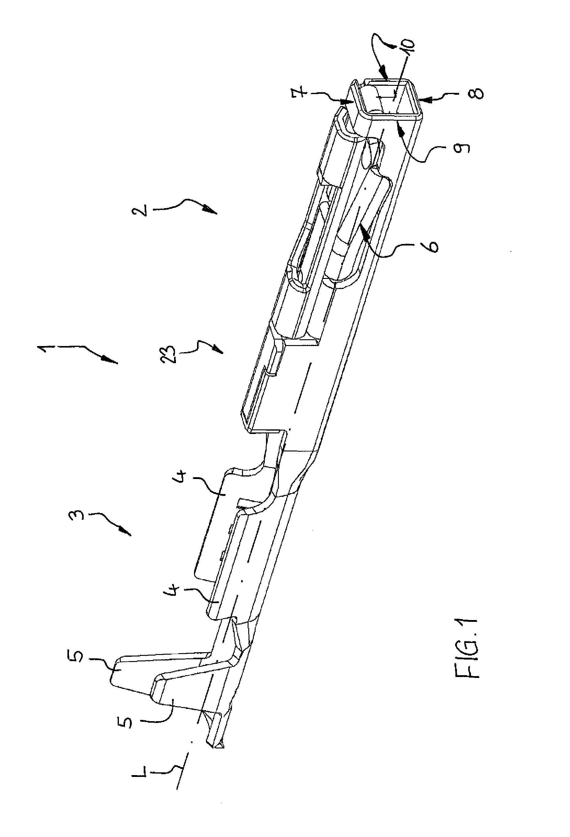
[0018]FIG. 1 shows a perspective view of an electric terminal 1 having a contact portion 2 and a connection portion 3. Between the connection portion 3 and the contact portion 2 there is provided a body portion 23. The electric terminal 1 is as a whole manufactured from a sheet-metal part by means of bending wherein the sheet metal part is made from an electrical conductive material, such as copper or a copper alloy. The connection portion 3 comprises two first crimping taps 4 for connecting an electrical conductor of a cable (not shown) to the electric terminal 1 by means of crimping. Furthermore, two second crimping taps 5 are provided on the side of the first crimping taps 4 which is opposite to the contact portion 2. The two second crimping taps 5 can be crimped to an insulation of the afore-mentioned cable.

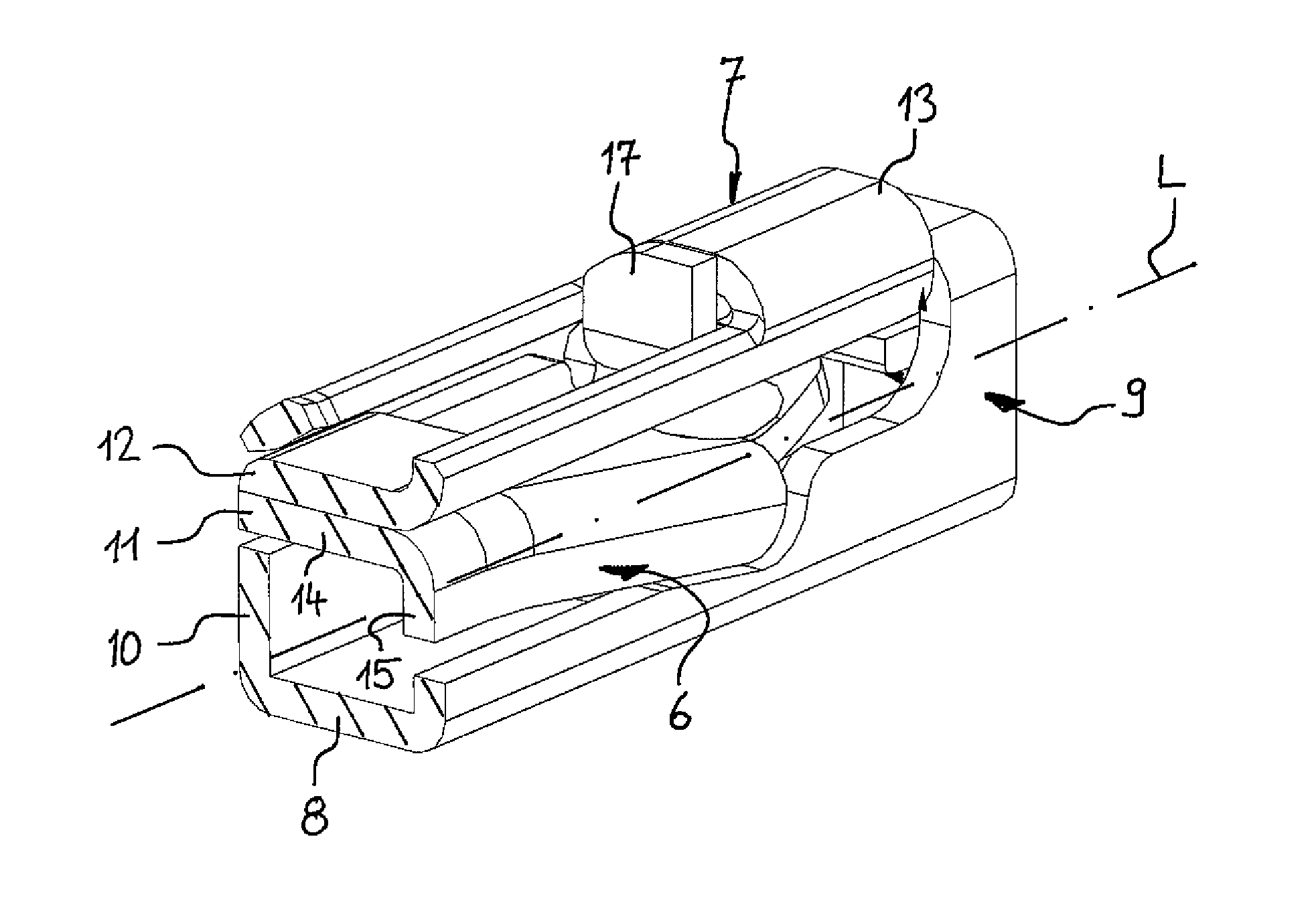
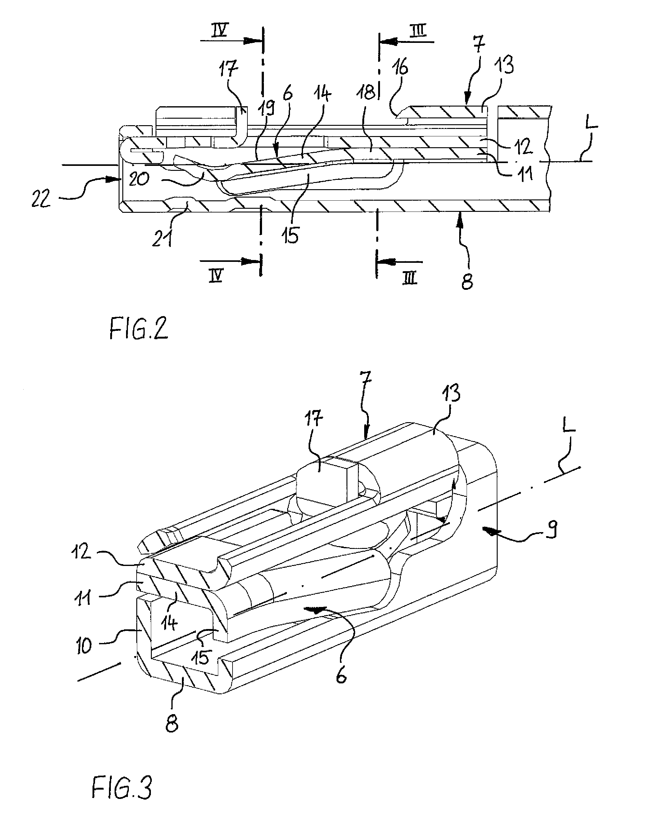
[0019]The contact portion 2 has a box shape with a hollow rectangular profile, wherein at an end thereof, which is facing away from the connection portion 3, a contact spring...


PUM


Abstract

An electric terminal (1) made of sheet metal having a contact portion (3) including a top wall (7), a bottom wall (8), a first side wall (9) and a second side wall (10) and a contact spring arm (6) having: a contact beam (14) for achieving an electric contact with a complementary contact element and being integrally connected to the top wall (7) and a reinforcement beam (15), wherein the contact beam (14) and the reinforcement beam (15) together form an L-shaped cross-section, wherein the reinforcement beam (15) is only connected to the contact beam (14).

Description

FIELD OF THE INVENTION[0001]The present invention relates to an electric terminal made of sheet metal having a contact portion comprising a top wall, a bottom wall, a first side wall and a second side wall. The contact portion further comprises a contact spring arm having a contact beam for achieving an electric contact with a complimentary contact element and being integrally connected to the top wall. The contact spring arm further has a reinforcement beam, wherein the contact beam and the reinforcement beam together form an L-shaped cross-section.BACKGROUND OF THE INVENTION[0002]Such an electric terminal is, for instance, known from EP 1 617 521 B1. The contact beam and the reinforcement beam are orientated perpendicular relative to each other achieving the L-shaped cross-section of the spring arm. The reinforcement beam is only connected to the contact beam at a tip end of the contact spring arm. At an opposite side of the tip end and of the contact spring arm the reinforcement ...

Claims


Application Information

Patent Timeline
Patent Type & Authority Patents(United States)
IPC IPC(8): H01R13/432H01R13/17H01R13/11H01R13/193H01R4/18H01R43/16
CPCH01R13/17H01R13/113H01R13/193H01R4/185H01R43/16
Inventor JAKOPLIC, IVICAJELAK, JOSIP
Owner YAZAKI EURO
Learn More