Antenna transfer switching for simultaneous voice and data

a technology of simultaneous voice and data and transfer switching, which is applied in the field of wireless communication devices, can solve the problem of not having enough physical volume to have two high-performance antennas

Active Publication Date: 2015-08-25
GOOGLE TECHNOLOGY HOLDINGS LLC
View PDF13 Cites 3 Cited by
  • Summary
  • Abstract
  • Description
  • Claims
  • Application Information

AI Technical Summary

Problems solved by technology

However, there may not be enough physical volume available to have two high performance antennas.

Method used


Image

  • Antenna transfer switching for simultaneous voice and data
  • Antenna transfer switching for simultaneous voice and data
  • Antenna transfer switching for simultaneous voice and data

Examples


first embodiment

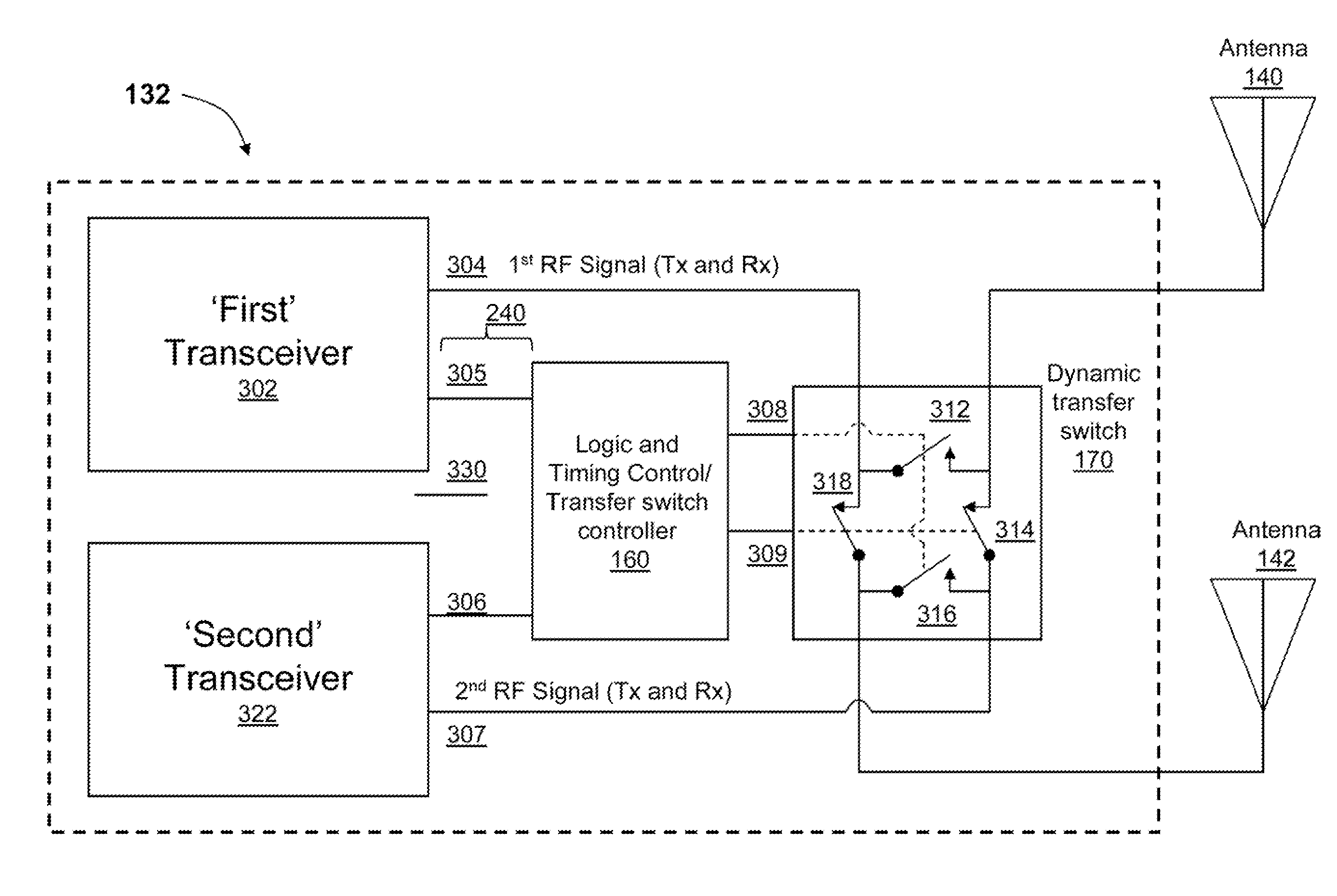
[0037]FIG. 3 is a block diagram illustrating Radio Frequency Front End (RFFE) Module 132 comprising a dynamic transfer switch 170 and a transfer switch (TS) controller 170160 which selectively configures the dynamic transfer switch, according to one embodiment. RFFE 132 comprises first transceiver 302 and second transceiver 322 which are both coupled electronically to TS controller 160. In addition, RFFE 132 also comprises dynamic transfer switch 170 which is coupled to transfer switch controller 160 which provides control signals to dynamic transfer switch 170. Transfer switch controller 160 is coupled to both first transceiver 302 and second transceiver 322 from which transfer switch controller 160 receives information 305 and 306 (e.g., information about a current operating mode and / or a currently initiated operating mode). Transfer switch controller 160 uses information 305 / 306 to configure dynamic transfer switch 170. In one embodiment, first transceiver 302 includes a first po...

second embodiment

[0044]FIG. 4 is a block diagram illustrating Radio Frequency Front End (RFFE) 132 comprising a dynamic transfer switch and a transfer switch controller which selectively configures the dynamic transfer switch, according to one embodiment. RFFE 132 comprises first transceiver 402 and second transceiver 422 which are both coupled electronically to transfer switch (TS) controller 160. In addition, RFFE 132 also comprises dynamic transfer switch 170 which is coupled to transfer switch controller 160 which provides control signals to dynamic transfer switch 170. In one embodiment, first transceiver 402 includes a first power amplifier (not shown) and a first duplexer (not shown) and second transceiver 422 includes a second power amplifier (not shown) and a second duplexer (not shown). Each of the first duplexer and the second duplexer has an input / output (I / O) port that is shared by transmit and receive signals. As illustrated in FIG. 4, first transceiver 402 provides a single RF signal ...

third embodiment

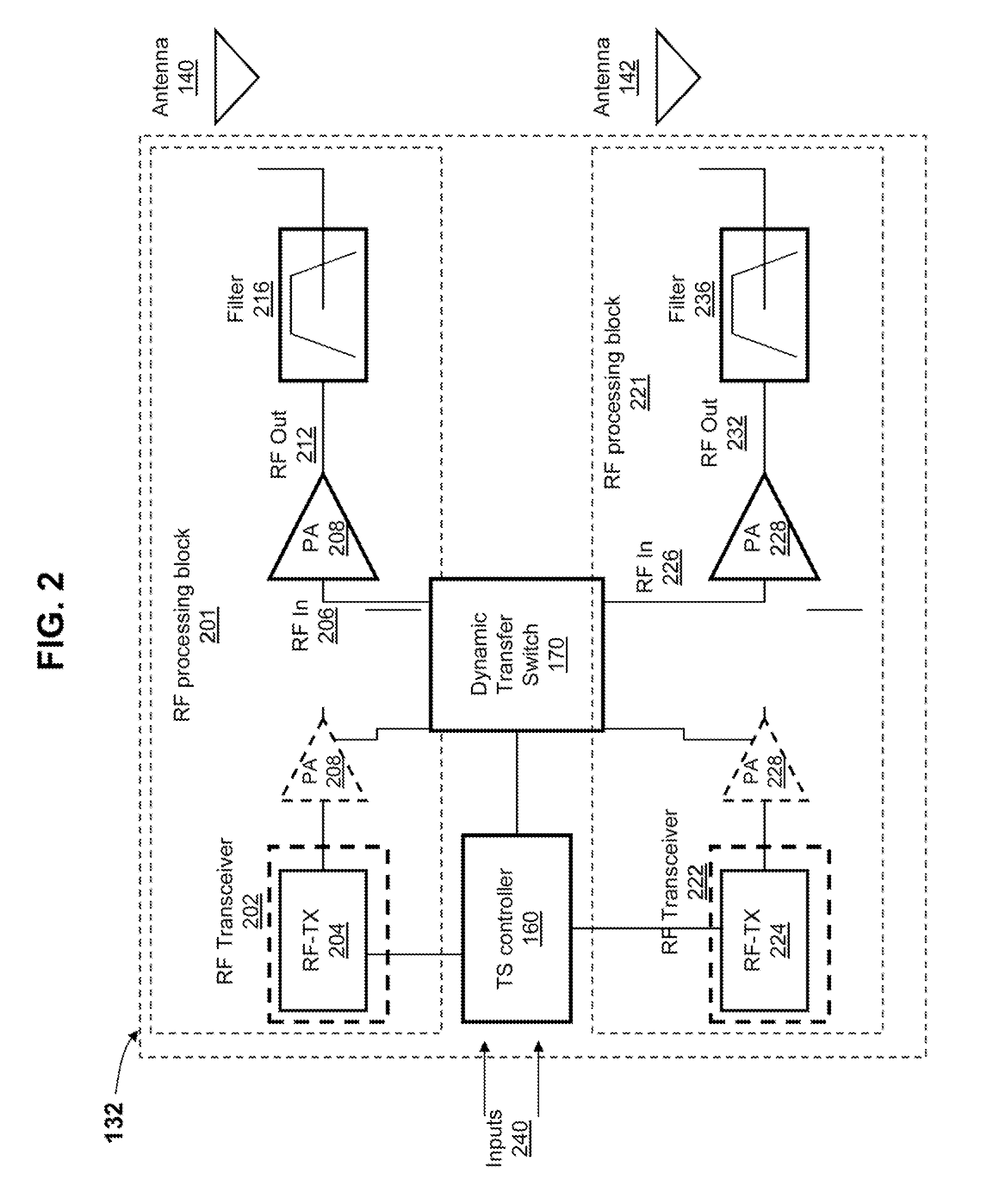
[0058]FIG. 5 is a block diagram illustrating Radio Frequency Front End (RFFE) Module 132 comprising a dynamic transfer switch and a transfer switch controller which selectively configures the dynamic transfer switch, according to one embodiment. RFFE 132 comprises first transceiver 502 and second transceiver 522 which are both coupled electronically to transfer switch controller 160. In addition, RFFE 132 also comprises dynamic transfer switch 170 which is coupled to transfer switch controller 160 from which dynamic transfer switch 170 receives control signals. Additionally, RFFE 132 comprises first power amplifier 508 and second power amplifier 528. Unlike the illustrations of FIGS. 3 and 4 in which the respective power amplifiers (and corresponding duplexers) are included within the corresponding transceiver blocks (and, as a result are not shown), FIG. 5 provides a more detailed illustration of RFFE 132 in which first power amplifier 508 and second power amplifier 528 (and corres...


PUM


Abstract

A method and system selects an antenna for signal propagation within a wireless communication device having multiple antennas. A transfer switch controller identifies an operating mode being initiated on the wireless communication device. The transfer switch controller configures a dynamic transfer switch based on the operating mode initiated to support propagation of each available type of communication signal. In addition, the transfer switch controller utilizes a pre-established priority of each available type of communication signal to select the appropriate antenna. The transfer switch controller communicatively connects, utilizing the configured dynamic transfer switch, each of at least one transceiver associated with the operating mode initiated to a specific antenna, where each transceiver supports propagation of a specific type of communication signal. As a result, the transfer switch controller enables each of the at least one communication signal to be propagated via a specific antenna selected using the configured dynamic transfer switch.

Description

BACKGROUND[0001]1. Technical Field[0002]The present disclosure relates in general to wireless communication devices, and relates in particular to radio frequency (RF) signal propagation in multi-antenna wireless communication devices.[0003]2. Description of the Related Art[0004]With an ever increasing demand for higher data rates accompanied by an increasing demand for higher signal quality, wireless communication systems have been increasingly employing various diversity antenna arrangements. In simultaneous voice and data (SVD) operations, separate antennas are generally used for voice and data. However, there may not be enough physical volume available to have two high performance antennas. As a result, system designers are still tasked with overcoming the challenges associated with signal quality even in these diversity arrangement configurations. Additionally, there is a need to avoid the occurrence of receiver desensitization due to inter-modulation of the simultaneously trans...

Claims


Application Information

Patent Timeline
Patent Type & Authority Patents(United States)
IPC IPC(8): H04B1/40H04M1/00H04B1/401
CPCH04B1/401H04B1/406
Inventor BLACK, GREGORY R.ALVEY, GRAHAM R.DUONG, MINH H.KULKARNI, JATIN A.
Owner GOOGLE TECHNOLOGY HOLDINGS LLC
Why Eureka
Try Eureka