Optical fiber having holes

a technology of optical fibers and holes, applied in the field of optical fibers, can solve the problems of limit on the increase of the effective area of single mode fibers, and achieve the effects of small bending loss, easy production, and great effective area

Active Publication Date: 2015-09-01
FUJIKURA LTD +1
View PDF14 Cites 3 Cited by
  • Summary
  • Abstract
  • Description
  • Claims
  • Application Information

AI Technical Summary

Benefits of technology

[0032]According to the present invention, it is possible to provide an optical fiber which (i) has a greater effective area and (ii) can be more easily produced as compared with a conventional photonic crystal fiber, while (a) being capable of carrying out a single mode transmission and (b) having a small bending loss as with the conventional photonic crystal fiber.

Problems solved by technology

However, there is limitation on increase in effective area of a single mode fiber, such as the single mode fiber described in Non-Patent Literature 1, in which the inner part of the clad region has a refractive index different from that of the outer part of the clad region by a dopant being added to the clad region.

Method used


Image

  • Optical fiber having holes
  • Optical fiber having holes
  • Optical fiber having holes

Examples


embodiment 1

[0055][Embodiment 1]

[0056]The following description will discuss Embodiment 1 of the present invention with reference to FIGS. 1 through 7.

[0057](Structure of Optical Fiber)

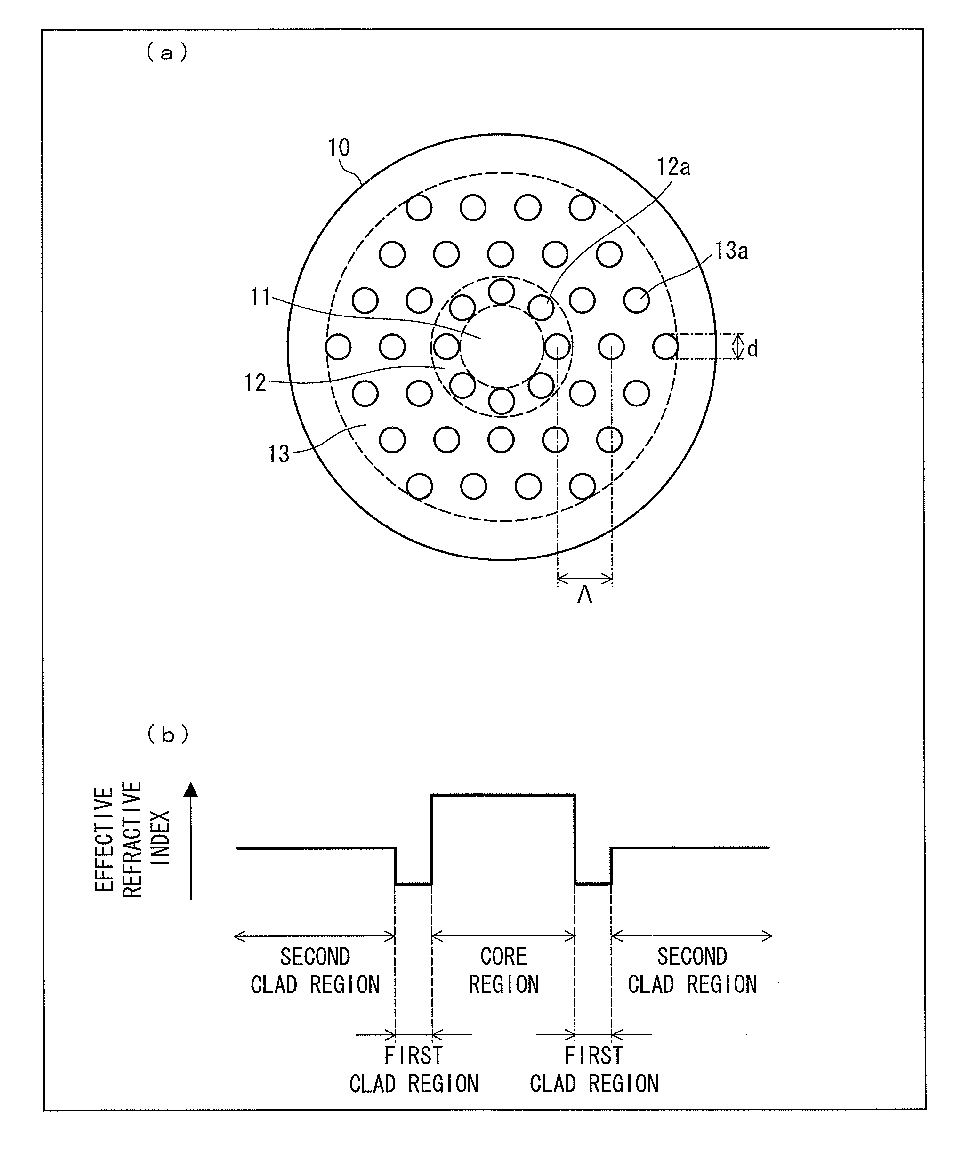
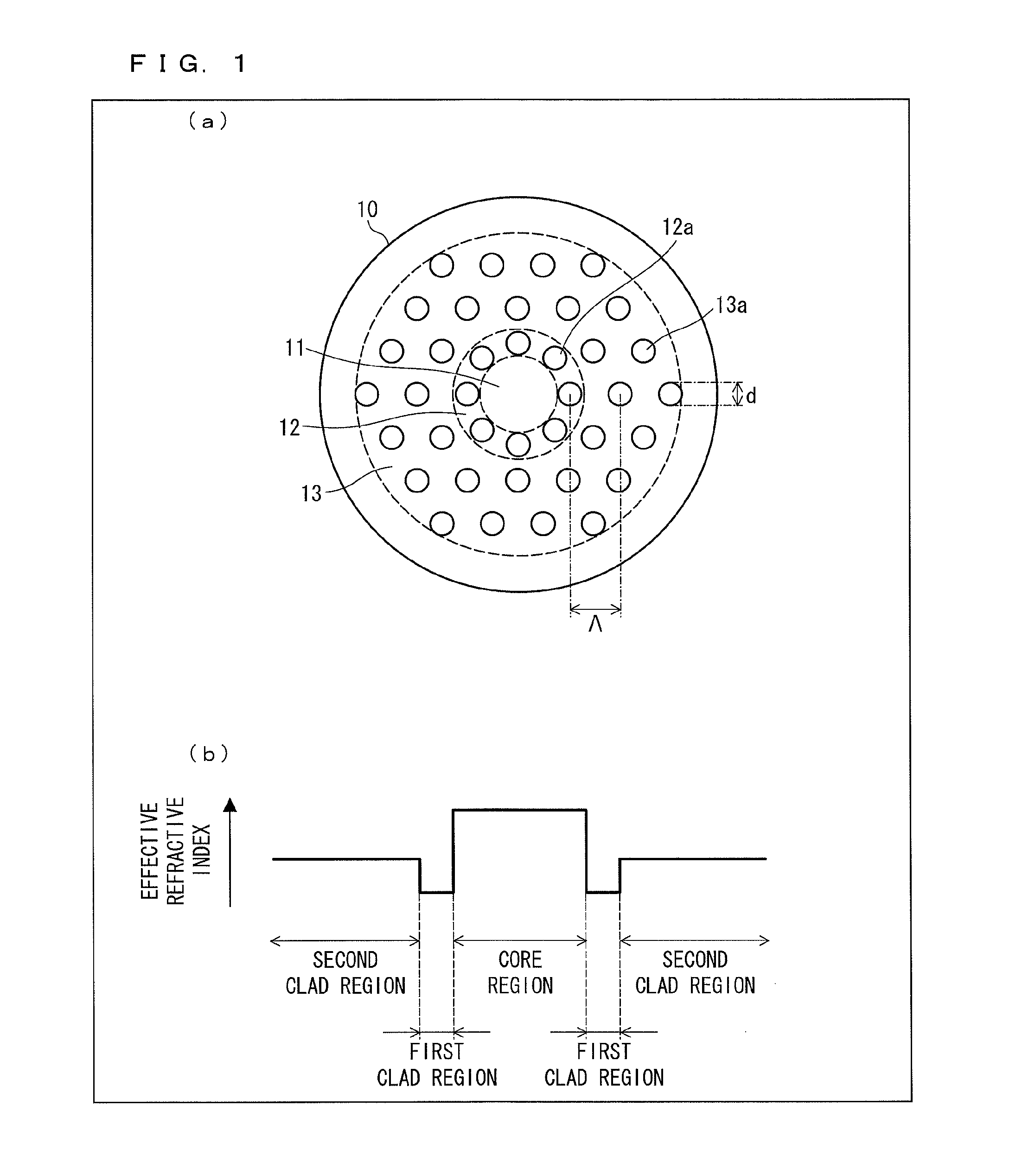
[0058]The following description will discuss a configuration of an optical fiber 10 in accordance with Embodiment 1, with reference to FIG. 1. (a) of FIG. 1 is a cross-sectional view illustrating a configuration of the optical fiber 10 in accordance with Embodiment 1. (b) of FIG. 1 is a graph showing an effective refractive index profile of the optical fiber 10 in accordance with Embodiment 1.

[0059]The optical fiber 10 has a cross sectional configuration in which (i) a core region 11 has a disk shape, (ii) a first clad region 12 has a ring shape that is arranged around the core region 11, and (iii) a second clad region 13 has a ring shape that is arranged around the first clad region 12 (see (a) of FIG. 1). The regions of the optical fiber 10 are made from respective identical materials (for example, pure silica ...

embodiment 2

[0092][Embodiment 2]

[0093]The following description will discuss Embodiment 2 of the present invention, with reference to FIGS. 8 through 10.

[0094](Configuration of Optical Fiber)

[0095]The following description will discuss a configuration of an optical fiber 10′ in accordance with Embodiment 2, with reference to FIG. 8. FIG. 8 is a cross-sectional view illustrating a configuration of the optical fiber 10′ in accordance with Embodiment 2.

[0096]The optical fiber 10′ has a cross sectional configuration in which (i) a core region 11′ has a disk shape, (ii) a first clad region 12′ has a ring shape that is arranged around the core region 11′, and (iii) a second clad region 13′ has a ring shape that is arranged around the first clad region′12 (see FIG. 8). Regions other than the first clad region 12′ of the optical fiber 10′ are made from respective identical materials (for example, pure silica glass).

[0097]The first clad region 12′ and the second clad region 13′ have holes 12′a and holes...


PUM


Abstract

Each of a first clad region (12) and a second clad region (13) has holes (12a, 13a) which have identical diameters and are periodically formed so that the first clad region (12) and the second clad region (13) each have an effective refractive index lower than a refractive index of a core region (11), the effective refractive index of the first clad region (12) being lower than that of the second clad region (13).

Description

CROSS-REFERENCE TO RELATED APPLICATIONS[0001]This application is a Continuation of PCT International Application Serial No. PCT / JP2011 / 051524 filed Jan. 26, 2011. This application is based upon and claims the benefits of priority from prior Japanese Patent Application No. 2010-015819 filed Jan. 27, 2010.TECHNICAL FIELD[0002]The present invention relates to an optical fiber, particularly relates to a photonic crystal fiber.BACKGROUND ART[0003]In an optical transmission system, it is important for an optical fiber, which is a transmission medium, to have an increased effective area so as to increase transmission quantity and a transmission distance. This is because the optical fiber having such an increased effective area can transmit intense optical signals without causing a decrease in transmission quality due to a nonlinear effect.[0004]An example of the optical fiber having such an increased effective area is a single mode fiber, which is described in Non-Patent Literature 1. The ...

Claims


Application Information

Patent Timeline
Patent Type & Authority Patents(United States)
IPC IPC(8): G02B6/036G02B6/032G02B6/02
CPCG02B6/02347G02B6/03627G02B6/02333
Inventor TANIGAWA, SHOJITAKENAGA, KATSUHIROMATSUO, SHOICHIROMATSUI, TAKASHISAKAMOTO, TAIJITSUJIKAWA, KYOUZOUTOMITA, SHIGERU
Owner FUJIKURA LTD
Why Eureka
Try Eureka