Capacitance type touch screen

a touch screen and capacitance technology, applied in the field of capacitance type touch screen, can solve the problem of limited range of the possible range of the pitch between the lead wirings arranged side by side, and achieve the effect of narrowing the pitch between the lead wirings

Active Publication Date: 2015-09-01
NISSHA PRINTING COMPANY
View PDF6 Cites 18 Cited by
  • Summary
  • Abstract
  • Description
  • Claims
  • Application Information

AI Technical Summary

Benefits of technology

[0025]Since the capacitance type touch screen is configured as described above, the position where the lead line wirings are formed is not limited to within the top plate of the cover lens, so that the inner edge of the decorat...

Problems solved by technology

Although the market has been demanding a further narrowing of the frame, the exten...

Method used


Image

  • Capacitance type touch screen
  • Capacitance type touch screen
  • Capacitance type touch screen

Examples


first embodiment

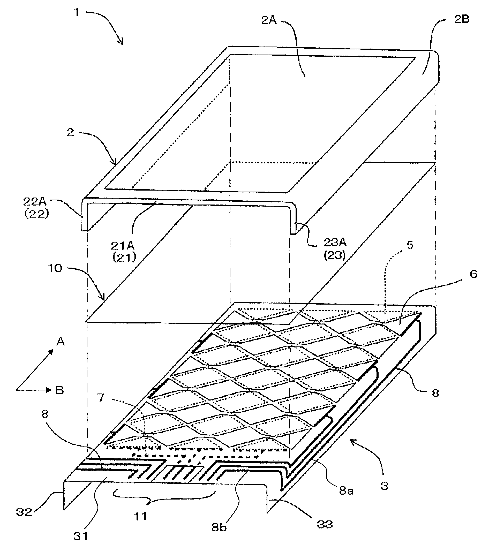
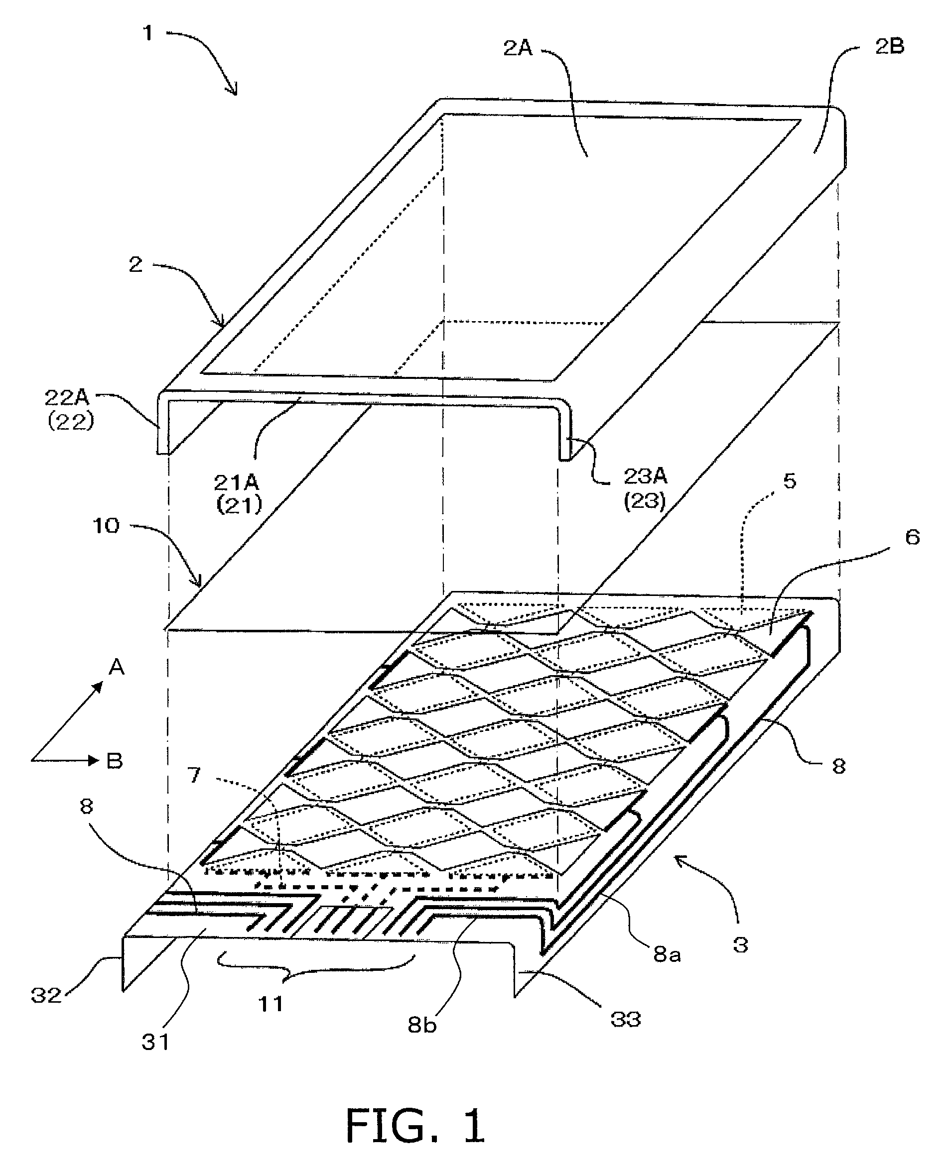
[0045]A touch screen 1 shown in FIG. 1 and FIG. 2 includes a cover lens 2, and a film sensor 3 adhered to a rear surface of the cover lens 2.

[0046]The cover lens 2 protects a display provided on a rear side of the cover lens 2 from external impact or the like. The cover lens 2 employs a casing structure composed of a rectangular top plate 21, a first side plate 22 of a thin rectangle connected to one side of the top plate 21, and a second side plate 23 of a thin rectangle connected to another side of the top plate 21 opposite to the first side plate 22. In this embodiment, the top plate 21 extends in A direction (first direction) in the figure, and the first side plate 22 and the second side plate 23 are connected to two sides of the top plate 21 along B direction (second direction), which is perpendicular to A direction. It should be noted that the top plate does not have to be rectangular, and the side plates do not have to be thin rectangles.

[0047]The top plate 21 of the cover le...

second embodiment

[0088]The touch screen 1 according to the present embodiment is different from one according to the first embodiment in that the size of the film sensor 3 is designed such that the lower end of the molded film sensor 3 is positioned lower than the lower ends of the first side plate 22 and second side plate 23 of the cover lens 2 (Refer to FIG. 3 and FIG. 4).

[0089]This configuration allows users to grab a portion sticking out from the cover lens 2 when the film sensor 3 is to be adhered to the cover lens 2, thereby improving the handling of the film sensor 3.

third embodiment

[0090]In the touch screen 1 according to the present embodiment, at least one of the first transparent electrodes 5 and the second transparent electrodes 6 may be present in the rising portions 32, 33 of the film sensor 3. In the present embodiment, both ends of the second transparent electrodes 6 extend to the rising portions 32, 33 (refer to FIG. 17), which is different from the first embodiment.

[0091]This configuration allows the sensing area to be formed beyond the outer periphery of the top plate 21, so that it becomes further ensured that the frame of the decorated area 2B in the top plate 21 is narrowed or that the decorated area 2B is frameless. In addition, the portion of the decorated area 2B that covers the first side plate 22 and the second side plate 23 can be utilized for inputting.

[0092]In the case where the transparent electrodes are also formed in the rising portions of the film sensor, it is preferable that the transparent electrodes are formed as a conductive patt...


PUM


Abstract

A capacitance type touch screen includes a cover lens and a film sensor. The film sensor includes a base film, first transparent electrodes arranged side by side extending in an A direction, second transparent electrodes insulated from the first electrodes and arranged side by side extending in B direction while crossing the first electrodes, a plurality of first lead wirings connected to the first electrodes and drawn to connection terminals, and a plurality of second lead wirings connected to the second electrodes and drawn to connection terminals. The first and second wirings are hidden by the cover lens decorated area. The film sensor includes a top-plate-corresponding-portion facing the cover lens top plate rear surface, and rising portions facing a rear surface of at least one of the first and second side plates. All or most of the second wirings is positioned in the rising portions.

Description

CROSS-REFERENCE TO RELATED APPLICATIONS[0001]This U.S. National stage application claims priority under 35 U.S.C. §119(a) to Japanese Patent Application No. 2011-080810, filed in Japan on Mar. 31, 2011, the entire contents of Japanese Patent Application No. 2011-080810 are hereby incorporated herein by reference.BACKGROUND[0002]1. Field of the Invention[0003]The present invention relates to a capacitance type touch screen exercising touch input function with a film sensor adhered to a rear surface of the cover.[0004]2. Background Information[0005]Conventionally, in personal digital assistants such as PDA and handy terminals, OA equipment such as copy machines, facsimiles, electronic devices such as smartphones, cellular phones, portable game devices, electronic dictionaries, car navigation systems, small PCs, and various household electrical appliances, a cover lens is provided in front of the liquid crystal display (LCD), in order to protect the surface of the liquid crystal displa...

Claims


Application Information

Patent Timeline
IPC IPC(8): G06F3/045G02F1/1333G06F3/044
CPCG06F3/044G06F1/16G06F3/0412G06F3/04164G06F3/0445G06F3/0446G02F1/13338
Inventor OMOTE, RYOMEIMATSUMURA, HIROAKI
Owner NISSHA PRINTING COMPANY
Why Eureka
Try Eureka