
Semiconductor light emitting device having multi-cell array and method of manufacturing the same

a light-emitting device and semiconductor technology, applied in the direction of semiconductor devices, basic electric elements, electrical appliances, etc., can solve the problems of accelerated deterioration of light efficiency, and difficulty in implementing a uniform current density for an entire area, so as to reduce the reduction of an effective light-emitting area and improve light efficiency.

Active Publication Date: 2015-09-01
SAMSUNG ELECTRONICS CO LTD
View PDF10 Cites 16 Cited by
  • Summary
  • Abstract
  • Description
  • Claims
  • Application Information

AI Technical Summary

Benefits of technology

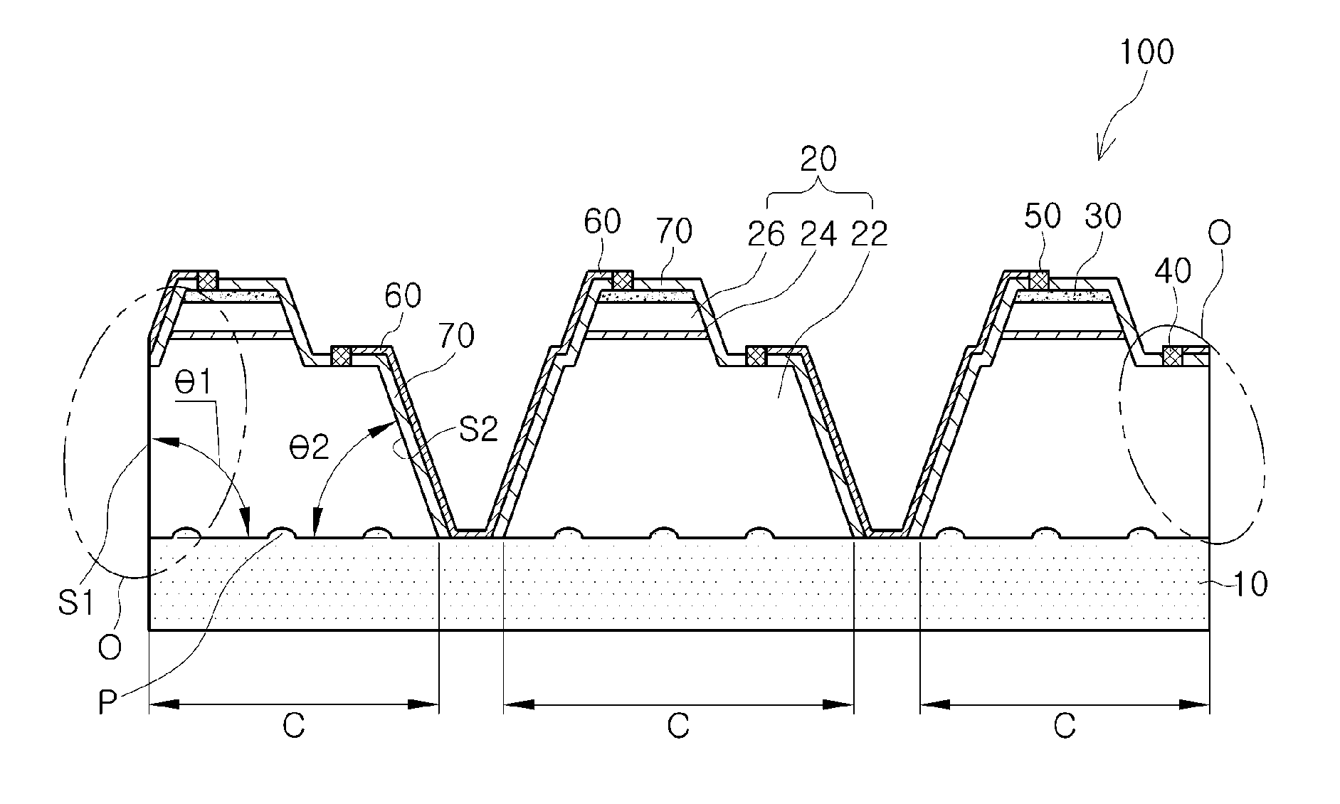
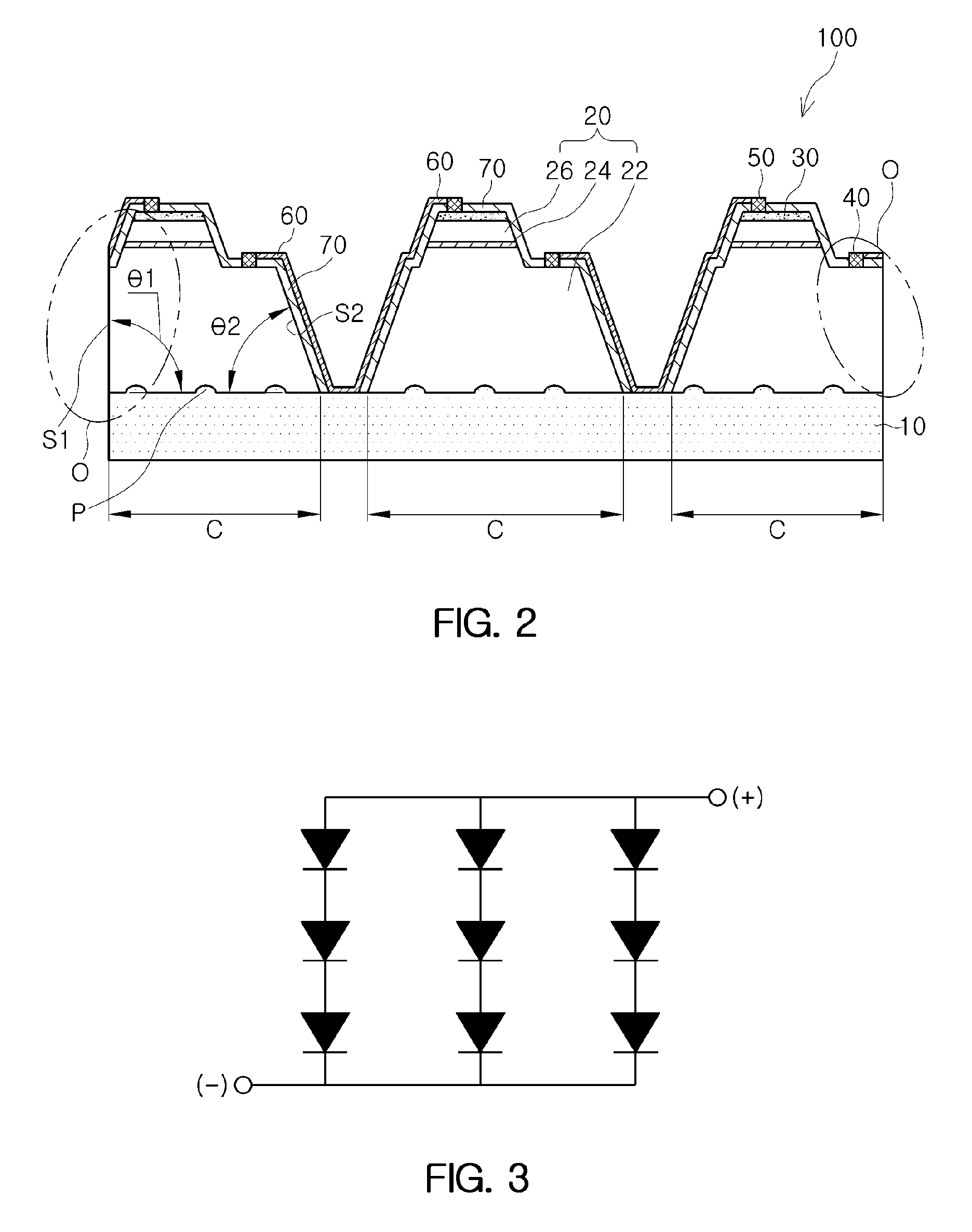
The present patent is about a semiconductor light emitting device that has a multi-cell array and a method of manufacturing it. This device can significantly improve light efficiency by reducing a reduction in effective light emission area caused by an isolation process.

Problems solved by technology

However, when increasing a rated current in order to increase speed of light in LED chips having the same area in a high output light emitting diode, light efficiency may be deteriorated due to an increase in a current density, and deterioration thereof may be accelerated due to a heat emission of devices.
On the other hand, in order to relieve the defect described above with respect to a current density, increasing an area of a light emitting diode chip may be considered, but it may be difficult to implement a uniform current density with respect to an entire area and to expect a high production yield.

Method used


Image

  • Semiconductor light emitting device having multi-cell array and method of manufacturing the same
  • Semiconductor light emitting device having multi-cell array and method of manufacturing the same
  • Semiconductor light emitting device having multi-cell array and method of manufacturing the same

Examples


Embodiment Construction

[0038]Hereinafter, exemplary embodiments of the present disclosure will be described in detail with reference to the accompanying drawings. The disclosure may, however, be embodied in many different forms and should not be construed as being limited to the exemplary embodiments set forth herein. Rather, these exemplary embodiments are provided so that this disclosure will be thorough and complete, and will fully convey a scope of the disclosure to those having ordinary skill in the art.

[0039]In the drawings, the shapes and dimensions of elements may be exaggerated for clarity, and the same reference numerals will be used throughout to designate the same or like elements.

[0040]A semiconductor light emitting device and a method of manufacturing the same according to an exemplary embodiment of the present disclosure will be described with reference to the accompanying drawings.

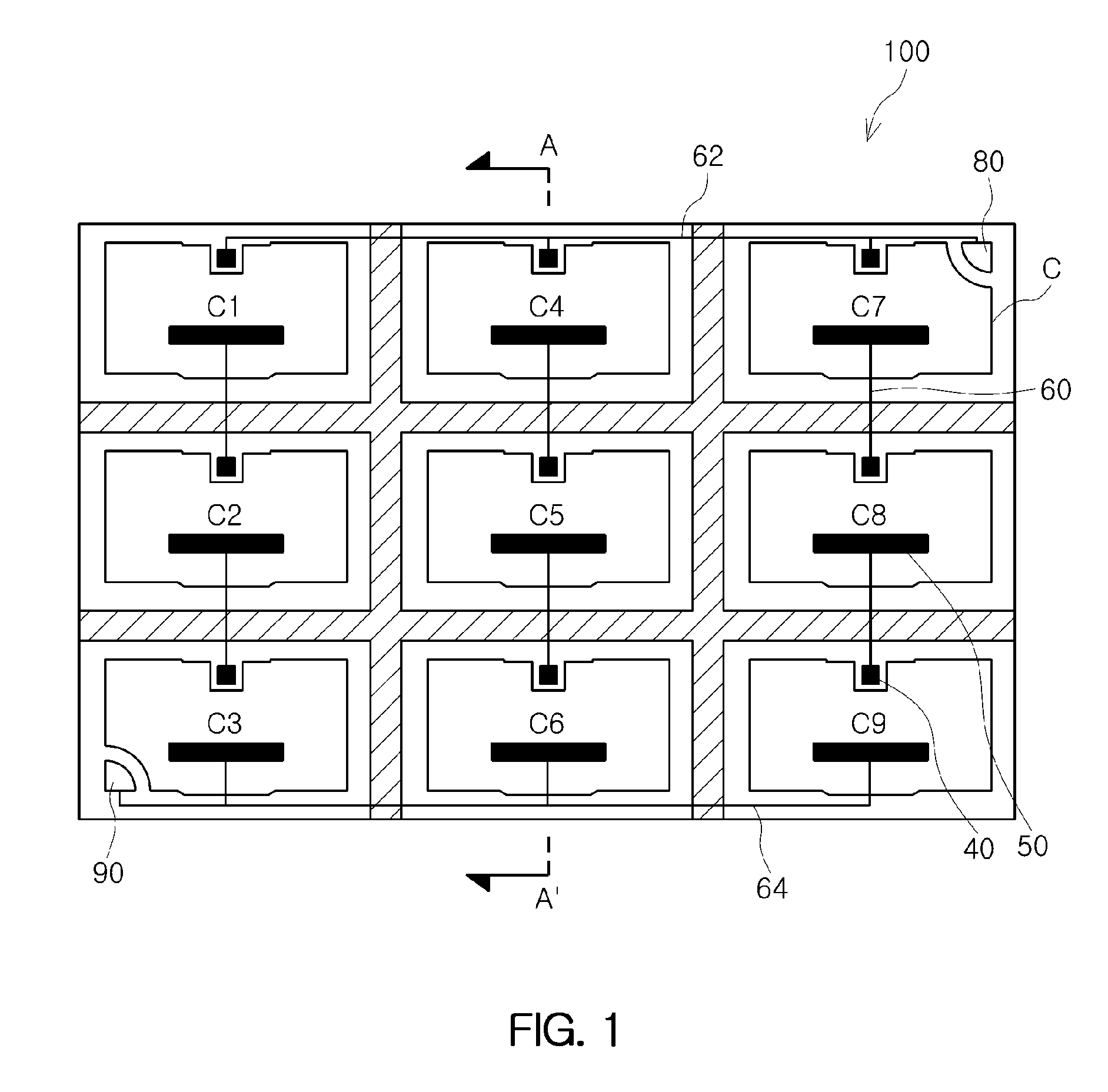
[0041]FIG. 1 is a top plan view of a semiconductor light emitting device having a multi-cell array according t...


PUM


Abstract

A method of manufacturing a semiconductor light emitting device having a multi-cell array, including: sequentially forming a first conductive semiconductor layer, an active layer and a second conductive semiconductor layer on a substrate; etching and removing portions of the second conductive semiconductor layer and the active layer so as to expose portions of an upper surface of the first conductive semiconductor layer corresponding to respective regions of the second conductive semiconductor layer spaced apart from one another; and separating light emitting cells by partially etching the exposed portions of the first conductive semiconductor layer, wherein the separating of the light emitting cells is not performed at an edge portion of the substrate.

Description

CROSS-REFERENCE TO RELATED APPLICATION[0001]This application claims the priority of Korean Patent Application No. 10-2012-0073511 filed on Jul. 5, 2012, in the Korean Intellectual Property Office, the entire disclosure of which is incorporated herein by reference.BACKGROUND OF THE DISCLOSURE[0002]1. Field of the Disclosure[0003]The present disclosure relates to a semiconductor light emitting device and a method of manufacturing the same.[0004]2. Description of the Related Art[0005]In general, a semiconductor light emitting diode (LED) has strengths as a light source in terms of high output, excellent light efficiency and reliability thereof. Therefore, research and development to allow for use of an LED as a high output and high efficiency light source in back light units for display devices and various illumination devices has been actively undertaken.[0006]In order to enable such an LED to be commercialized as a light source for lighting, there is a need to increase light efficien...

Claims


Application Information

Patent Timeline
Patent Type & Authority Patents(United States)
IPC IPC(8): H01L29/15H01L33/00H01L27/15H01L33/20
CPCH01L27/15H01L27/156H01L33/005H01L33/20H01L2933/0016H01L33/08H01L33/22H01L33/48H01L33/62
Inventor JO, SU HYUNLEE, JONG HOLEE, JIN HYUNLIM, CHAN MOOKKIM, JIN HWAN
Owner SAMSUNG ELECTRONICS CO LTD
Learn More