Chest height light emission system

a light emission system and chest height technology, applied in the field of chest height light emission system, can solve the problems of inability to wear a device by a person, inability to provide illumination for activities to increase visibility, and inability to achieve the effect of reducing the stress on the head and neck muscles, avoiding temporary blindness, and reducing the reduction of visual acuity

Inactive Publication Date: 2009-08-04
BARKER PAUL H
View PDF25 Cites 14 Cited by
  • Summary
  • Abstract
  • Description
  • Claims
  • Application Information

AI Technical Summary

Benefits of technology

[0013]Another significant object of the illumination invention can be to provide a portable illumination device worn at chest height. Establishing the illumination device at chest height avoids contact between the illumination device and the arms or legs of the wearer. Additionally, establishing the illumination device at a chest height location avoids blocking of the light emitted by the illumination device by the arm or legs of the wearer. Importantly, establishing the illumination device at chest height location couples travel of the field of illumination to movement of the chest height location and uncouples travel of the field of illumination from movement of other parts of the wearer's body, such as the head, neck, legs, or arms. For example, establishing the illumination device at a chest height location on the front of a wearer can generate a field of illumination having a location relative to the wearer which remains substantially fixed even though the head or other parts of the wearer's body may be in motion. Another advantage of establishing the illumination invention at chest height can be a reduction in the stress on head and neck muscles.
[0014]Another significant object of the illumination invention can be to provide a portable illumination invention which conditions the response of the eye to avoid temporary blindness or lessen reduction in visual acuity, or maintain visual acuity due to a rapid increase or decrease in light intensity incident upon the eye.

Problems solved by technology

Despite the high demand which continues to drive development of additional illumination devices and the numerous and varied illumination devices already available in the marketplace, a number of problems with respect to providing illumination for activities to increase visibility remain unresolved.
A significant problem with conventional portable illumination devices can be that the device cannot be worn by a person or cannot be worn for certain activities.
; however, the configuration, size or weight of the conventional illumination device makes impractical using the illumination device for rigorous activities such as hiking, climbing, bicycling, or running as disclosed for example by U.S. Pat. Nos. 3,953,722; 4,319,309; 4,328,533;
Another significant problem with conventional portable illumination devices can be that the device is worn at the waist of a person as disclosed for example by U.S. Pat. Nos. 4,112,482; 4,283,756; 4,521,832; 4,523,258; 4,652,981; or 4,812,953.
One aspect of this problem can be that illumination devices worn at waist level can interfere with the movement of the legs of the wearer.
Another aspect of this problem can be that the illumination cast by an illumination device established at waist height can in whole or part be blocked or obscured by the movement of the arms or the legs.
As such, the field of illumination may not properly located (whether at all times or part of the time) for the wearer to visualize the path of travel.
Another significant problem with conventional portable illumination devices can be that the device is worn on the head or neck as disclosed for example by U.S. Pat. Nos. 4,231,079; 3,944,803; 5,268,826.
One aspect of this problem can be that the configuration or weight of the conventional illumination device worn on the head or neck can cause strain on the head or neck muscles.
Another aspect of this problem similar to that above-described can be that the location of the field of illumination may be coupled to movement of the head or neck.
Again, the field of illumination may not properly located (whether at all times or part of the time) for the wearer to visualize the path of travel.
Yet another significant problem with conventional portable illumination devices can be insufficient illumination of the area of activity.
A first aspect of the problem may be an insufficient radiance of the light source or amount of energy released from the light source.
Another aspect of this problem may be insufficient illuminance or intensity or degree to which the area of activity is illuminated.
For example, the angle of the light emitted relative to the field of illumination may not be optimal when the illumination device is worn on the head, neck, or at waist height and as described above may lack constancy as to location due to movement of as above-described.
Still another significant problem with conventional portable illumination devices can be that the device does not provide sufficient illumination of the wearer's eyes.
When the eye is conditioned to a level of light an increased illuminance upon the eye can be blinding because the iris cannot contract rapidly enough to reduce the light incident to the retina.
Additionally, the iris of the eye can overreact to the increased illuminance reducing the amount of light incident to the retina for a duration of time.
As such, when the work or recreational activity performed makes the eye incident to rapid increases in illuminance, the person can be blind or have lowered visual acuity for such duration of time.
For example, a person running or walking at night may be temporarily blinded by the light of oncoming automobiles.
During that period of temporary blindness, the runner or walker being unable to see or having lowered visual acuity for a duration of time, in which several steps may be taken when walking or running, can be at increased risk of injury.

Method used


Image

  • Chest height light emission system
  • Chest height light emission system
  • Chest height light emission system

Examples


Embodiment Construction

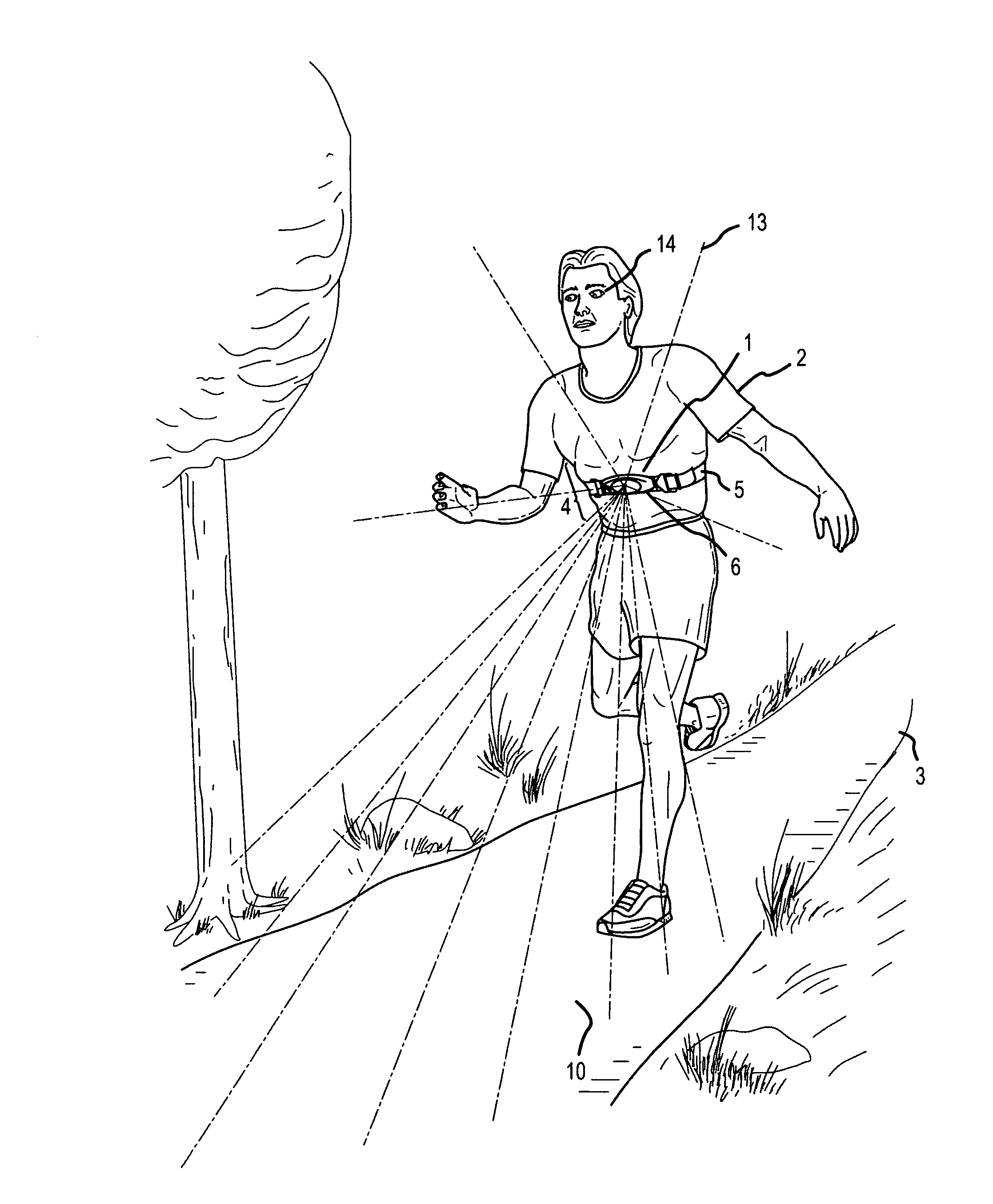
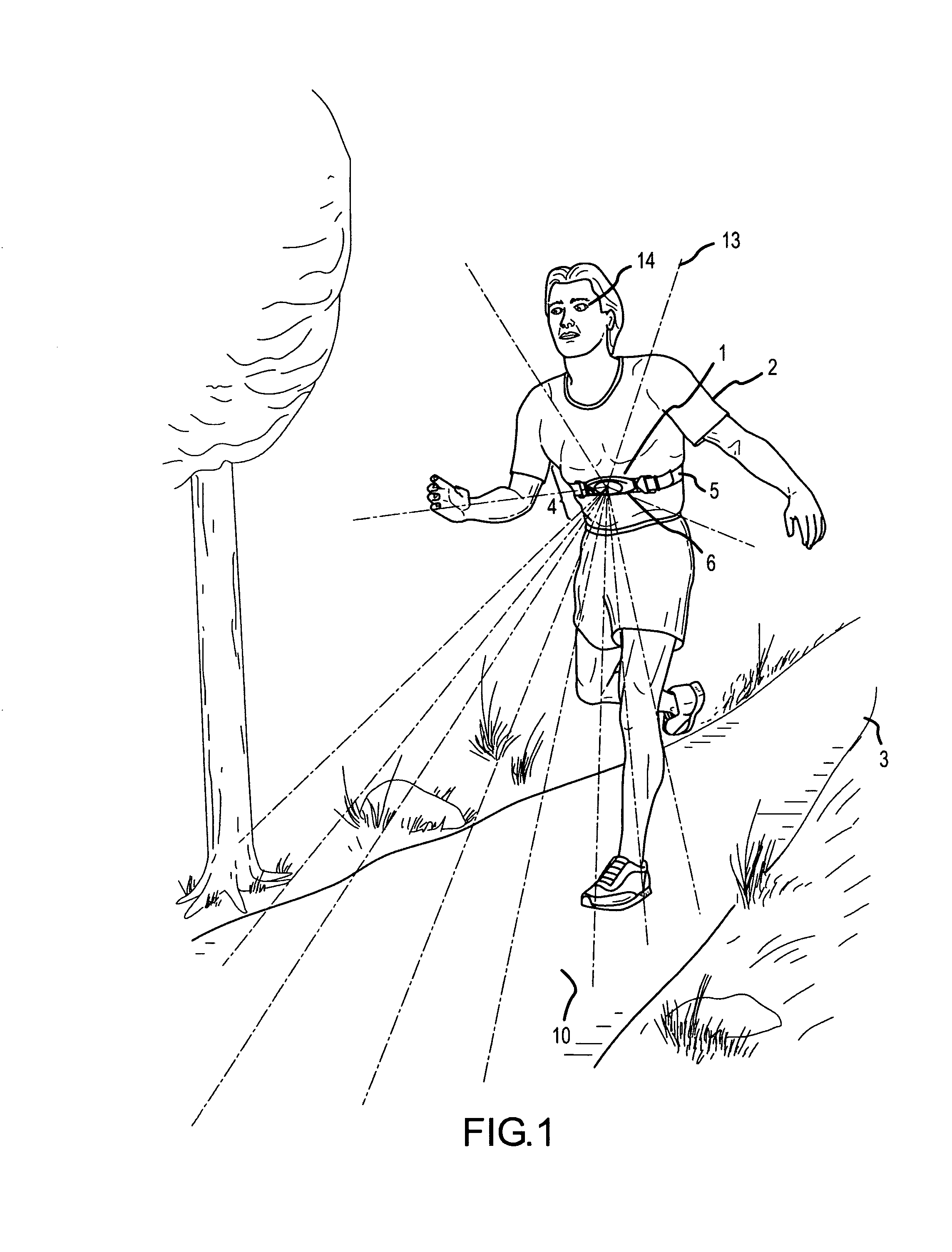
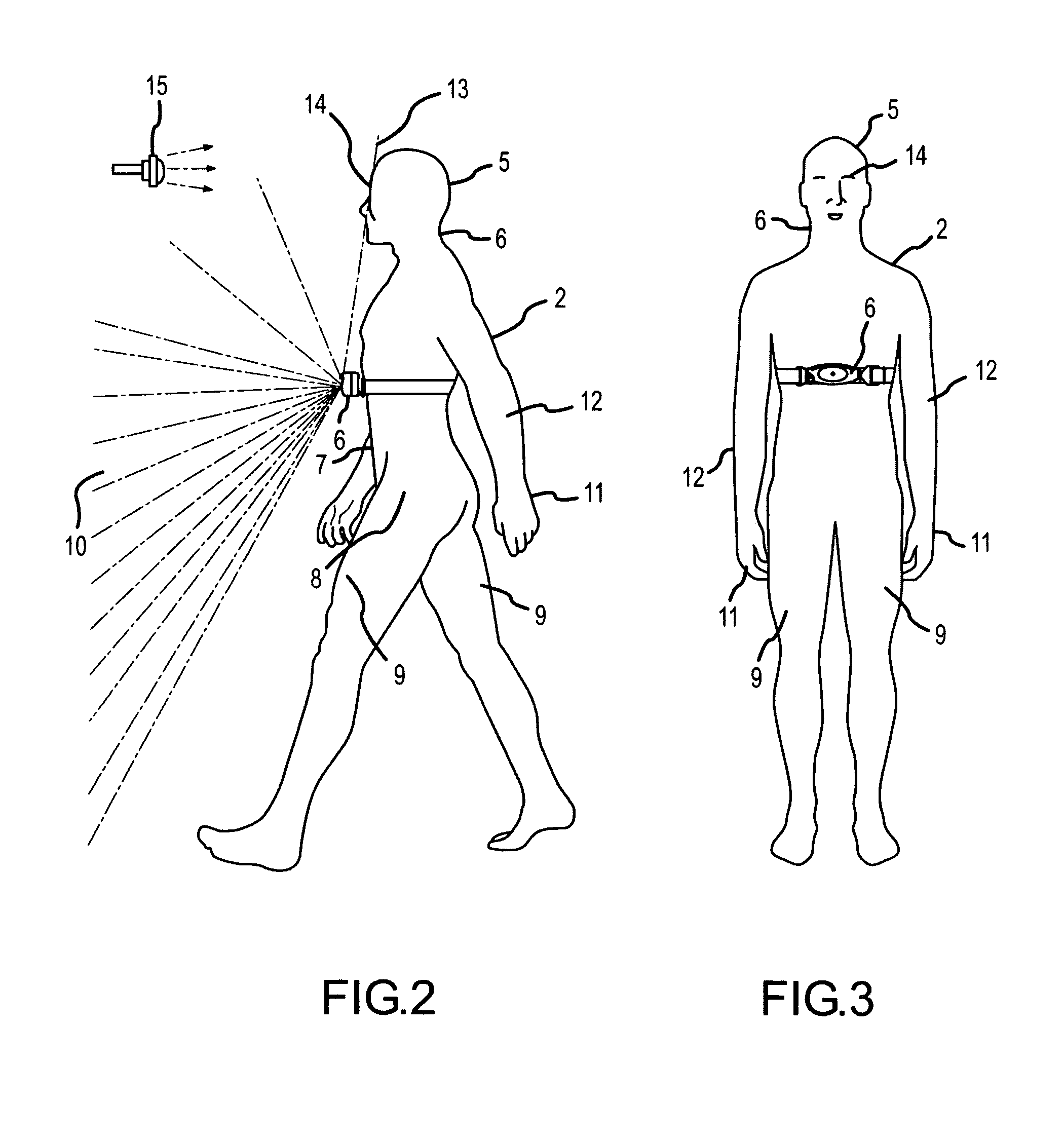
[0033]A preferred embodiment of the inventive illumination device can be worn at chest height to illuminate the area proximate to the wearer. Now referring primarily to FIG. 1, the illumination device (1) can be worn by a person (2) (or wearer) to illuminate a path (3) in the direction of travel. As to this preferred embodiment of the invention the illumination invention (1) can be established at chest height (4)(as described below) by adjusting a restraint (5) connected to an illumination assembly (6). The term “chest height” generically encompasses the tubular region of a person between about the level of the armpits and about the level of naval (above the waist). The term is not intended to be limiting with respect to the location at which the illumination assembly can be established on the tubular region of the wearer and the illumination assembly can be established on the front side, the back side, or at any other desired location on the tubular region each being a chest height...


PUM


Abstract

An illumination device worn at chest height to illuminate an area proximate to the wearer.

Description

[0001]This United States Patent Application claims the benefit of U.S. Provisional Patent Application No. 60 / 691,375, filed Jun. 17, 2005, hereby incorporated by reference herein.I. BACKGROUND[0002]A light emission system for illumination of an area proximate to the wearer.[0003]Various work and recreational activities are performed outside between dusk and dawn, inside buildings insufficiently lit for certain activities, or otherwise in insufficiently lit environments which necessitate or make desirable the use of an illumination device to increase the amount of light. Due to the prevalence of activities in which additional light is desired, there is a high demand for portable illumination sources which remain stationary or are worn on the body. This demand has spawned a numerous and wide variety of illumination devices such as those disclosed by U.S. Pat. Nos. 3,944,803; 3,953,722; 4,112,482; 4,231,079; 4,283,756; 4,319,309; 4,451,871; 4,521,832; 4,522,258; 4,652,981; 4,774,642; 4...

Claims


Application Information

Patent Timeline
Patent Type & Authority Patents(United States)
IPC IPC(8): F21V7/08
CPCF21V21/145F21L4/04
Inventor BARKER, PAUL H.
Owner BARKER PAUL H
Why Eureka
Try Eureka