Tire conveyor for a tire testing machine

a technology of tire conveyor and tire testing machine, which is applied in the direction of rolling-way, structural/machine measurement, vehicle testing, etc., can solve the problems of degrading running performance, achieve stable transfer, reduce cost, and achieve the elevation of the roller portion reliably and smoothly

Inactive Publication Date: 2015-09-08
KOBE STEEL LTD
View PDF4 Cites 2 Cited by
  • Summary
  • Abstract
  • Description
  • Claims
  • Application Information

AI Technical Summary

Benefits of technology

[0010]According to the above-described configuration, the elevation mechanism may move the placement surface of the roller portion upward and downward relative to the conveying surface of the conveyor or move the conveying surface of the conveyor upward and downward relative to the placement surface of the roller portion by driving only one actuator provided in one portion movable upward and downward. Thus, the roller portion or the conveyor is reliably and smoothly elevated without synchronizing the plurality of actuators, and hence the tire may be stably transferred between the conveyor and the roller portion.
[0012]Since the air cylinder is used as the actuator, the elevation mechanism may be realized simply at low cost.
[0013]According to the tire conveyor of the present invention, the tire may be stably transferred between the conveyor and the roller portion by reliably and smoothly realizing the elevation of the roller portion.

Problems solved by technology

When a tire attached to an automobile or the like includes a portion having a non-uniform elastic modulus, a non-uniform dimension, or a non-uniform shape in the circumferential direction, the portion causes a vibration during the high-speed rotation of the tire, and hence degrades the running performance thereof.

Method used


Image

  • Tire conveyor for a tire testing machine
  • Tire conveyor for a tire testing machine
  • Tire conveyor for a tire testing machine

Examples


Embodiment Construction

[0025]Hereinafter, embodiments of a tire conveyor according to the present invention for a tire testing machine will be described based on specific examples with reference to the drawings.

[0026]Furthermore, the description below is merely an example, and does not limit the application of the tire conveyor according to the present invention. That is, the tire conveyor according to the present invention is not limited to the embodiments below, and may be modified into various forms without departing from the scope of claims.

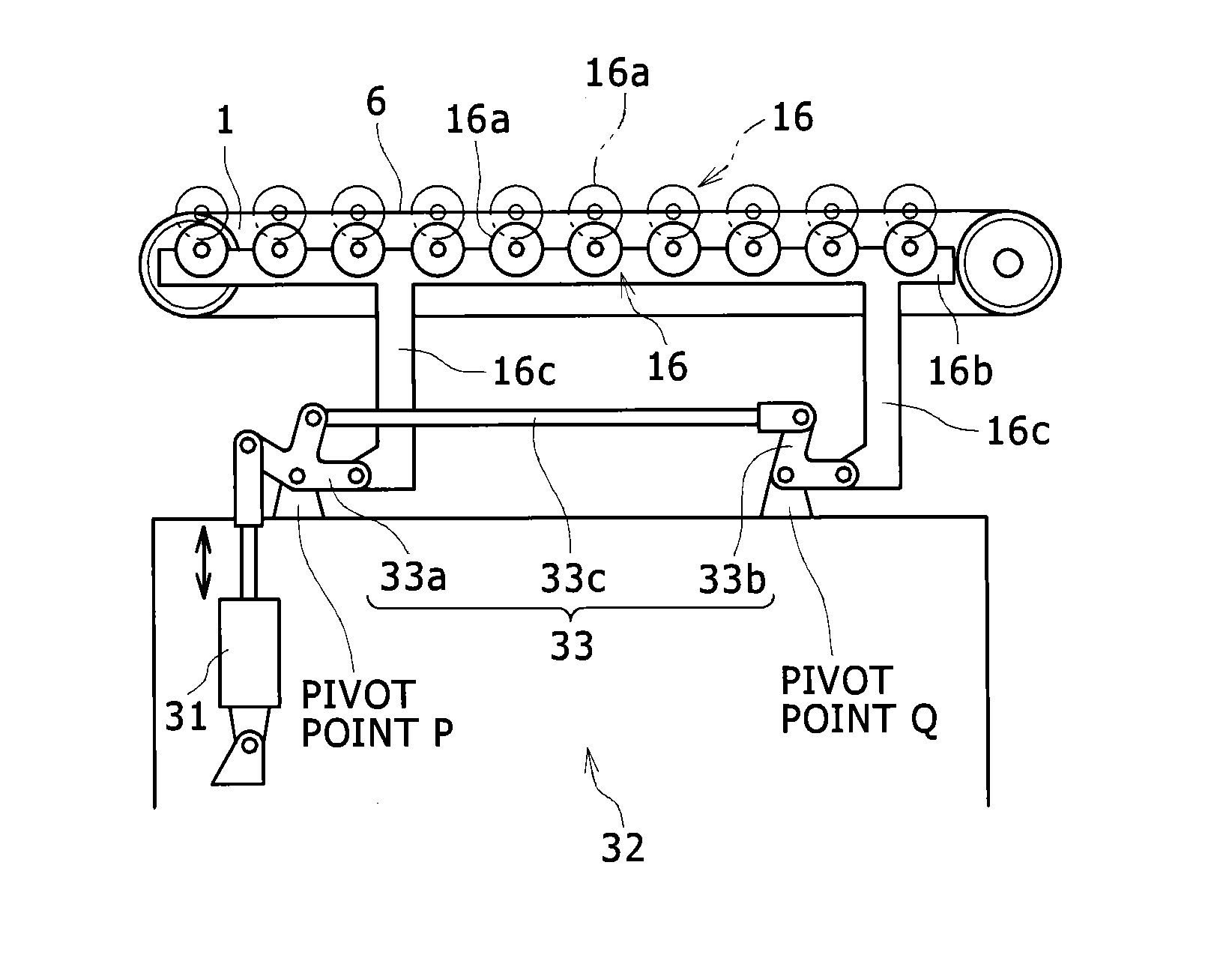
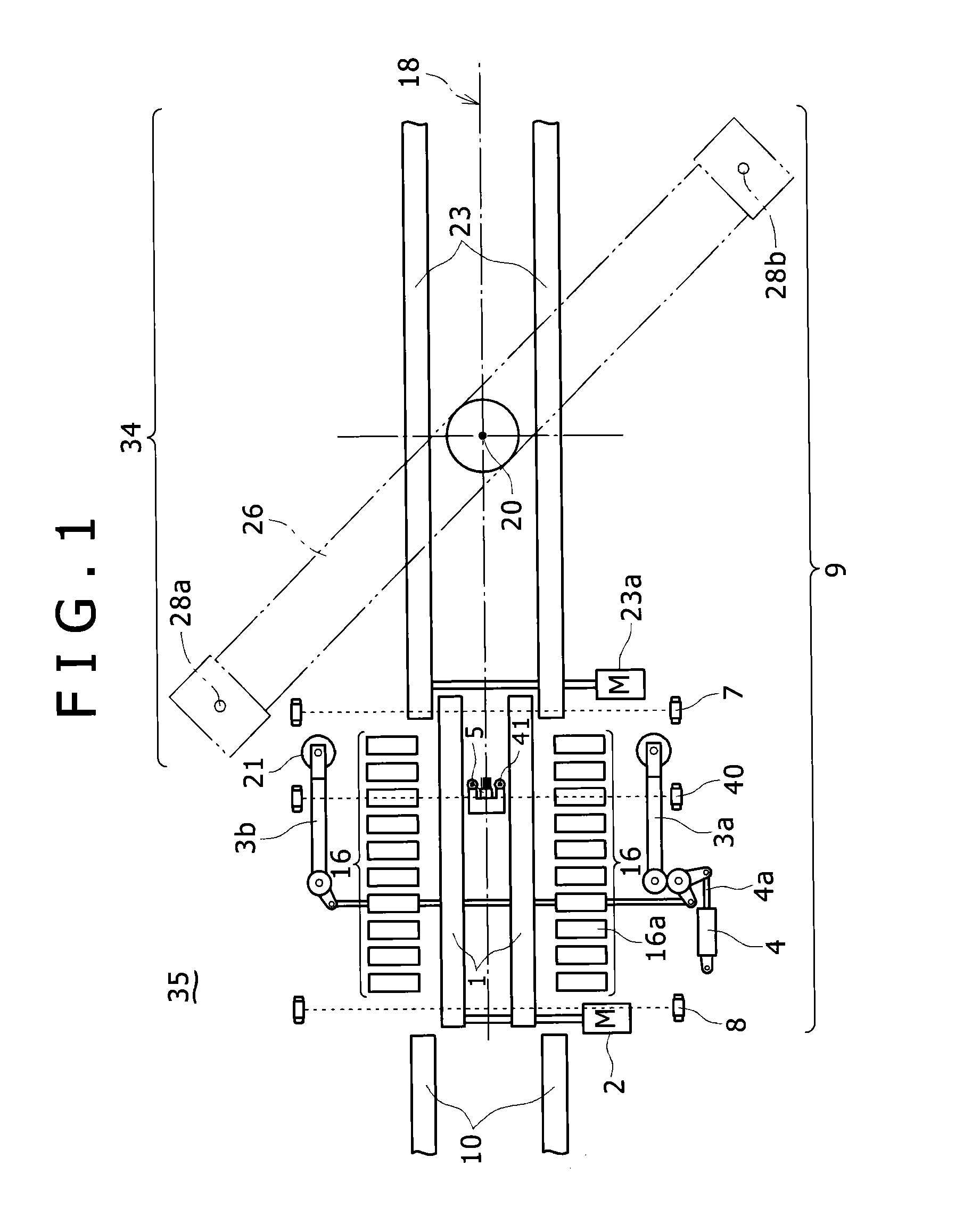
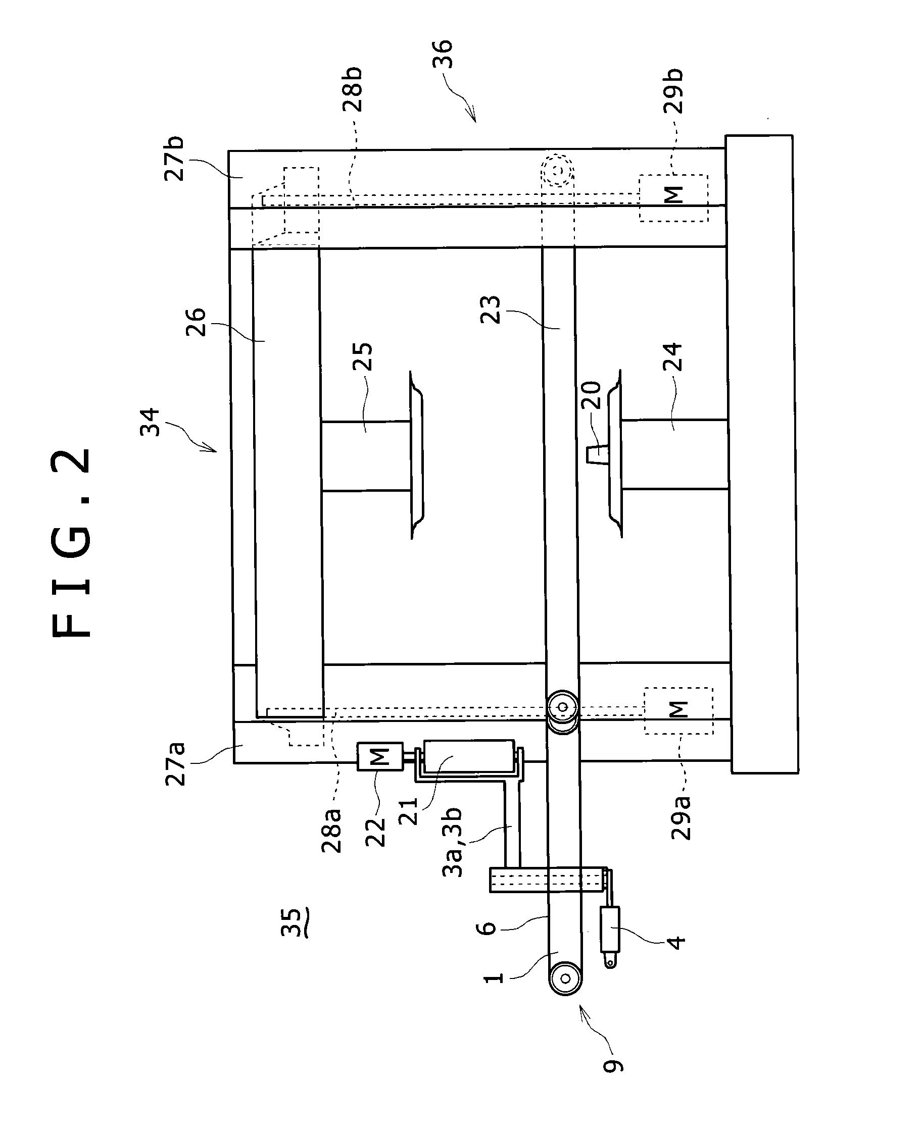
[0027]As illustrated in FIGS. 1 to 3, a tire conveyor 9 that is used in a tire testing machine 35 according to this embodiment includes an entrance conveyor 1 as a first belt conveyor that conveys a tire 11 conveyed and input from a customer conveyor 10 in a reclined state and a center conveyor 23 as a second belt conveyor that is connected to the downstream side of the entrance conveyor 1 and extends inside a test station 34.

[0028]One shaft of the entrance conveyo...


PUM


Abstract

A tire conveyor includes a roller portion provided at a position, in the width direction perpendicular to the conveying direction, without a conveying surface. The roller portion extends parallel to the conveying surface and is provided with a plurality of placement rollers forming a placement surface on which the tire is rotatably placed. An elevation mechanism includes a single actuator and a link mechanism connecting the roller portion or the conveyor to the actuator in a supported state and moves the placement surface of the roller portion upward and downward relative to the conveying surface by driving the actuator.

Description

BACKGROUND OF THE INVENTION[0001]1. Field of the Invention[0002]The present invention relates to a tire conveyor that sends a tire to a tire testing machine.[0003]2. Description of the Related Art[0004]When a tire attached to an automobile or the like includes a portion having a non-uniform elastic modulus, a non-uniform dimension, or a non-uniform shape in the circumferential direction, the portion causes a vibration during the high-speed rotation of the tire, and hence degrades the running performance thereof. For this reason, the tire is subjected to a uniformity test in the circumferential direction by a tire testing machine after the tire is made by vulcanizing. Specifically, the tire testing machine fits a bead portion of the inner periphery of the tire into a rim member, attaches the tire to a rotating spindle, applies a predetermined pressure to the tire, rotationally drives a road surface substitution member such as a drum while the outer periphery of the tire is pressed ag...

Claims


Application Information

Patent Timeline
Patent Type & Authority Patents(United States)
IPC IPC(8): B65G47/244G01M17/02B65G13/02
CPCB65G13/02G01M17/021
Inventor WAKAZONO, TAKEHIKOSOEJIMA, MUNENORI
Owner KOBE STEEL LTD
Why Eureka
Try Eureka