Container filling device

a container and container technology, applied in the direction of metal sawing devices, liquid handling, manufacturing tools, etc., can solve the problems of non-related art, difficult positioning of containers below the particular operating station, and heavy machine itsel

Active Publication Date: 2015-09-08
HAMBA FILLTEC
View PDF21 Cites 21 Cited by
  • Summary
  • Abstract
  • Description
  • Claims
  • Application Information

AI Technical Summary

Benefits of technology

[0013]Thus, it is the object of the invention to provide an alternative device for filling containers in which also support elements that are not connected with one another can be accelerated and decelerated in a controlled manner in the main elements.
[0023]Thus it is preferred when the operating element is a gear which engages a gear rack of the support element in a form locking manner for providing controlled acceleration or deceleration. It is furthermore provided that the upper main element or the lower main element include down holders which prevent an upsetting of the support elements under a controlled acceleration or deceleration.
[0025]Eventually it is provided for friction minimization that the support elements are run through the device on rollers.

Problems solved by technology

The non related art, however, also has substantial disadvantages which were so far accepted as necessary limitations when operating filling devices.
One of the disadvantages is the chain which elongates during operation which makes positioning the containers below the particular operating stations difficult.
Another essential disadvantage is caused by the required massive drive elements which have substantial weight and through which the masses to be accelerated of respectively configured drives require supports etc.
Overall the machine itself is very heavy and a plurality of high quality and expensive components needs to be installed and disassembled and uninstalled or replaced during maintenance.
This does not only cause substantial material and component expense during production and maintenance.
Substantial production shortfalls have to be accepted when the equipment is maintained.
The solution sketched out in EP 1 495 997 B1, however, has a significant disadvantage.

Method used


Image

  • Container filling device
  • Container filling device
  • Container filling device

Examples


Embodiment Construction

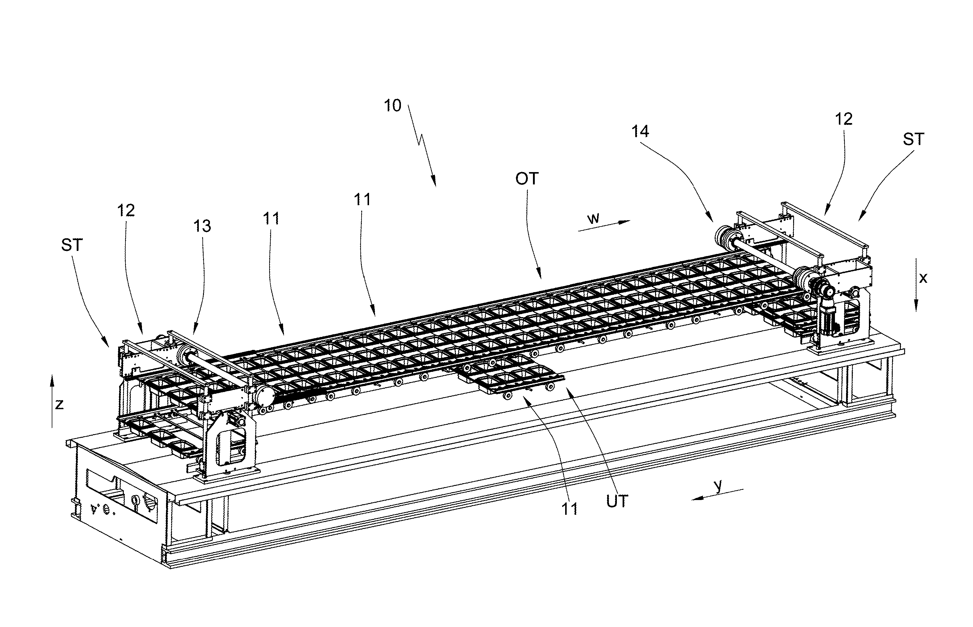
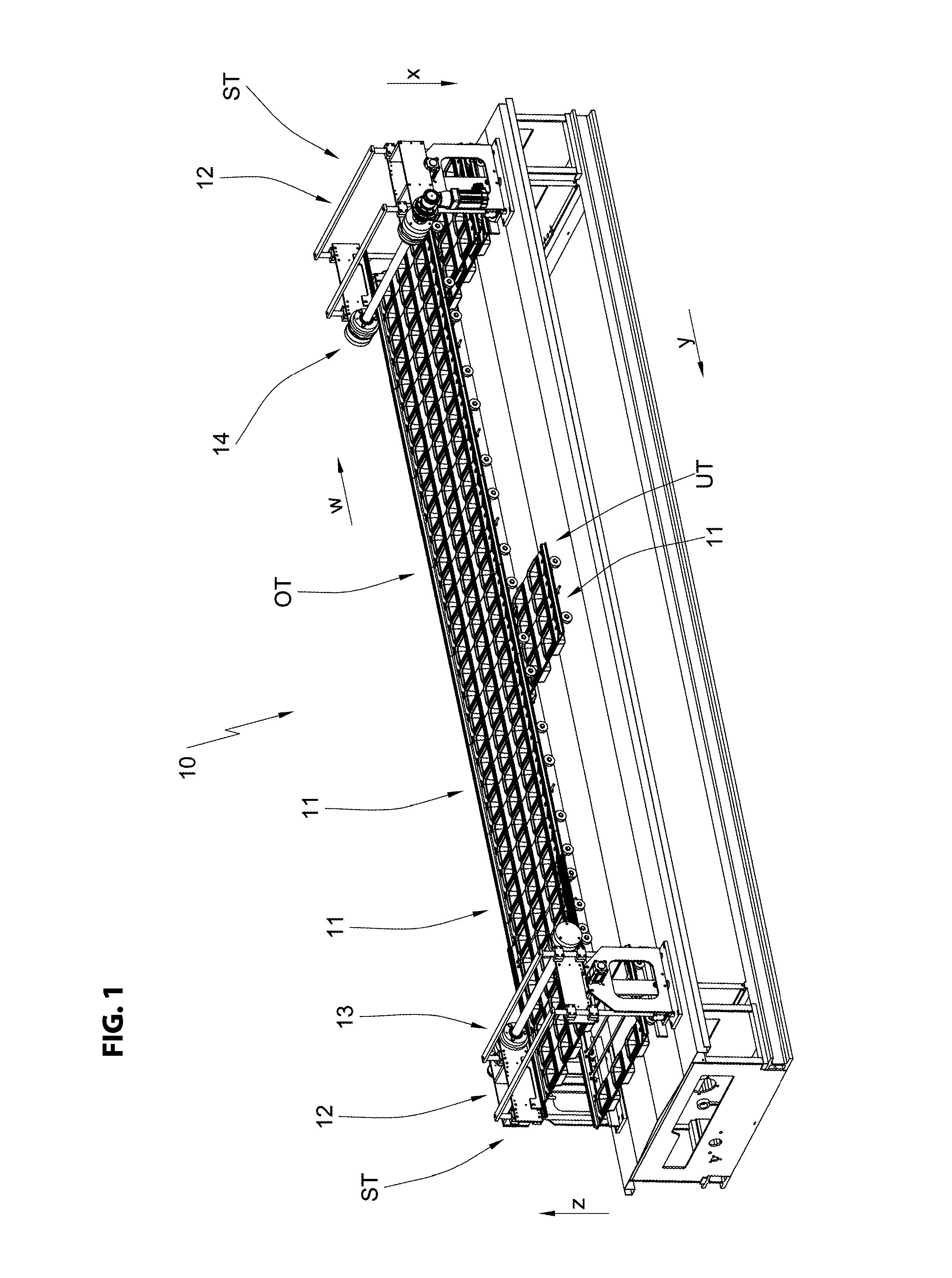
[0031]In the FIGs. a device according to the invention is designated overall with the reference numeral 10. The device 10 is a filling device for free flowing to pasty food products like e.g. margarine, milk products or juices.

[0032]The device 10 with respect to a placement surface includes a horizontal upper main element OT and a horizontal lower main element UT. The upper main element OT and the lower main element UT are subsequently also designated as main elements or main element. The upper main element OT and the lower main element UT are connected with one another through two lateral elements ST which are presently configured as elevators.

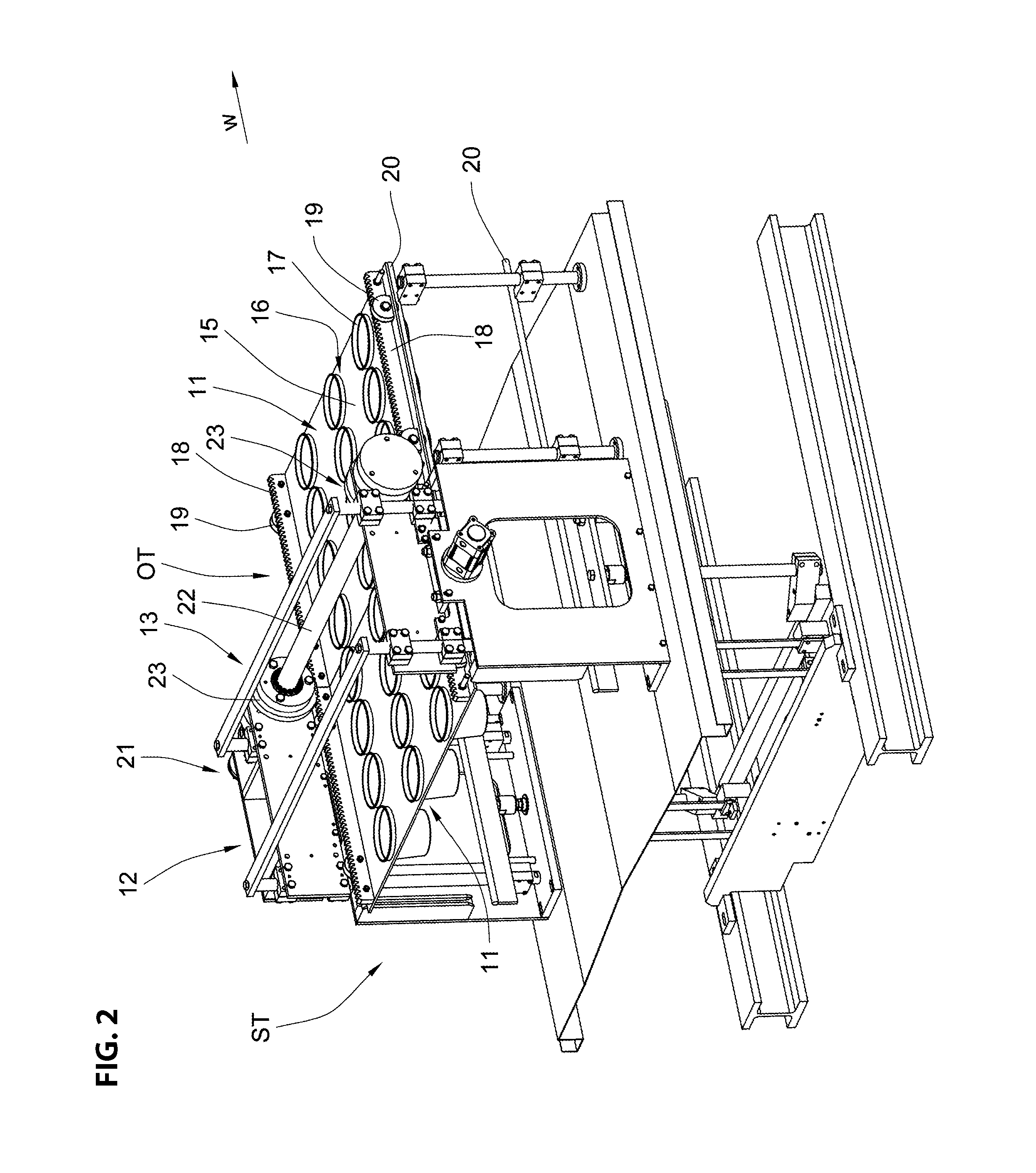
[0033]Along the elements OT, UT and ST particular carts 11 are continuously supported. These carts 11 are vertically moved from the upper main element OT into the lower main element UT and back by the elevators 12 forming the lateral elements ST. In particular it is implemented that each cart arranged in the upper main element OT is moved in ...


PUM

PropertyMeasurementUnit
movementaaaaaaaaaa
forcesaaaaaaaaaa
accelerationaaaaaaaaaa

Abstract

A device for filling containers, comprising: an upper main element, a lower main element and lateral elements connecting the upper main element and the lower main element;support elements arranged at one another without a continuous drive device, which support elements are continuously run through the device along operating stations and along the main elements and whose interconnection with one another due to a support along at least one lateral element is disengaged, wherein the interconnection of the support elements with one another in the upper main element and / or in the lower main element is maintained over the entire movement path along the top main element and the bottom main element, and wherein the movement of the support elements in the upper main element and / or in the lower main element is acceleratable and deceleratable in a controlled manner with the interconnection of the support elements being maintained.

Description

RELATED APPLICATIONS[0001]This application claims priority from and incorporates by reference German patent application DE 10 2011 103 152.2 filed on May 25, 2011FIELD OF THE INVENTION[0002]The present invention relates to a device for filling containers, in particular bottles or beakers with food products, in particular liquid to paste-like dairy and fat products, juices, waters and similar, including an upper main element, a lower main element and lateral elements connecting the upper and the lower main element, a plurality of support elements arranged at one another without a continuous drive device, which support elements are run in an endless manner through the device past operating stations and along the main elements and the lateral elements, wherein an interconnection of the support elements with one another is disengaged due to the support elements being supported along at least one lateral element.BACKGROUND OF THE INVENTION[0003]Typically the containers to be filled accor...

Claims


Application Information

Patent Timeline
Patent Type & Authority Patents(United States)
IPC IPC(8): B65G35/08B65B65/02B65B43/52B65B43/54B67C3/24
CPCB67C3/24B65B43/52B65B43/54B65B65/02B65G35/08
Inventor JUNK, MARTIN
Owner HAMBA FILLTEC
Why Eureka
Try Eureka