
Acoustic drying system with interspersed exhaust channels

a drying system and exhaust channel technology, applied in drying machines, drying, light and heating equipment, etc., can solve problems such as inacceptable coating artifacts or image artifacts, and achieve the effects of reducing the length of acoustic air impingement, improving drying uniformity, and improving drying

Inactive Publication Date: 2015-09-08
EASTMAN KODAK CO
View PDF36 Cites 2 Cited by
  • Summary
  • Abstract
  • Description
  • Claims
  • Application Information

AI Technical Summary

Benefits of technology

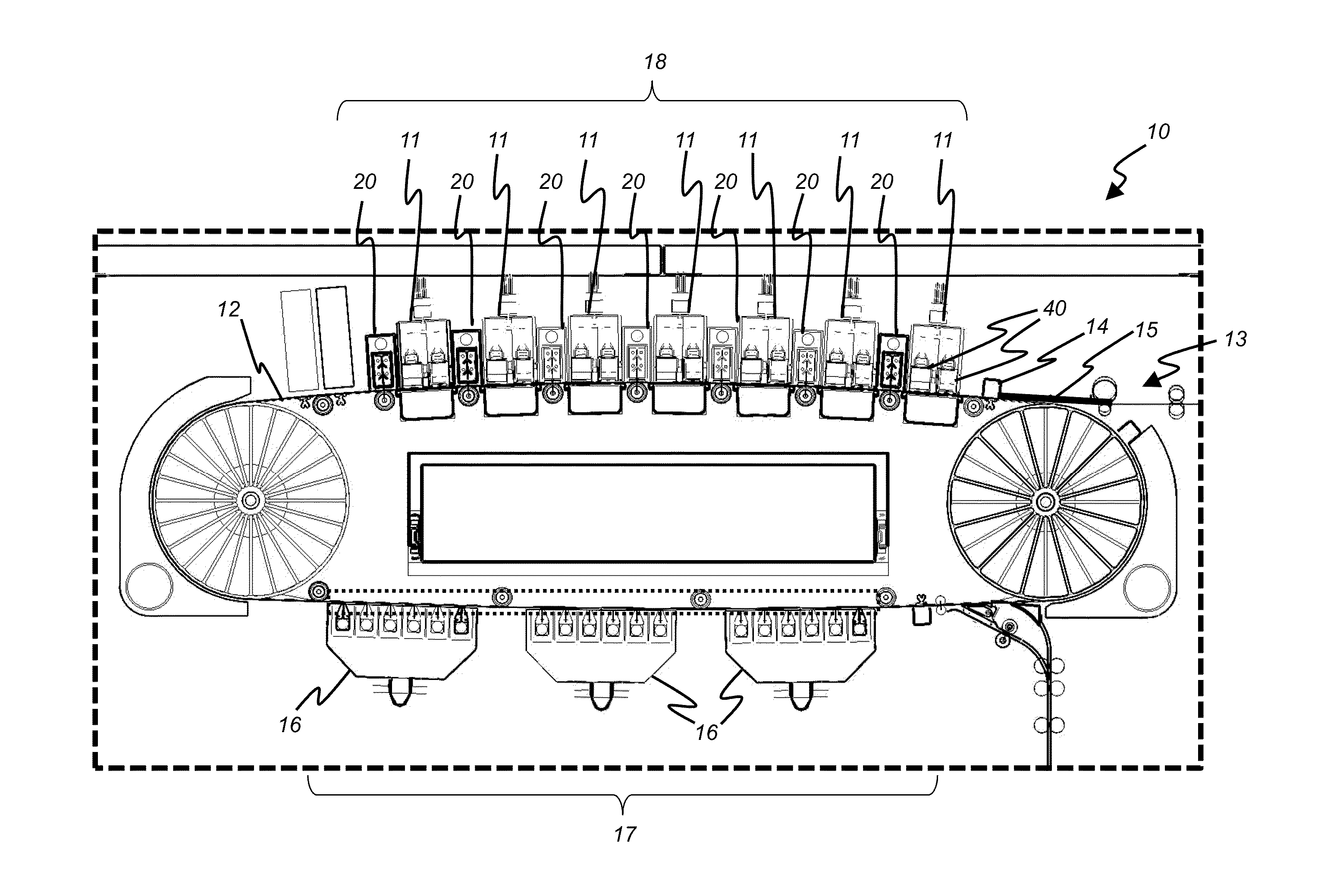
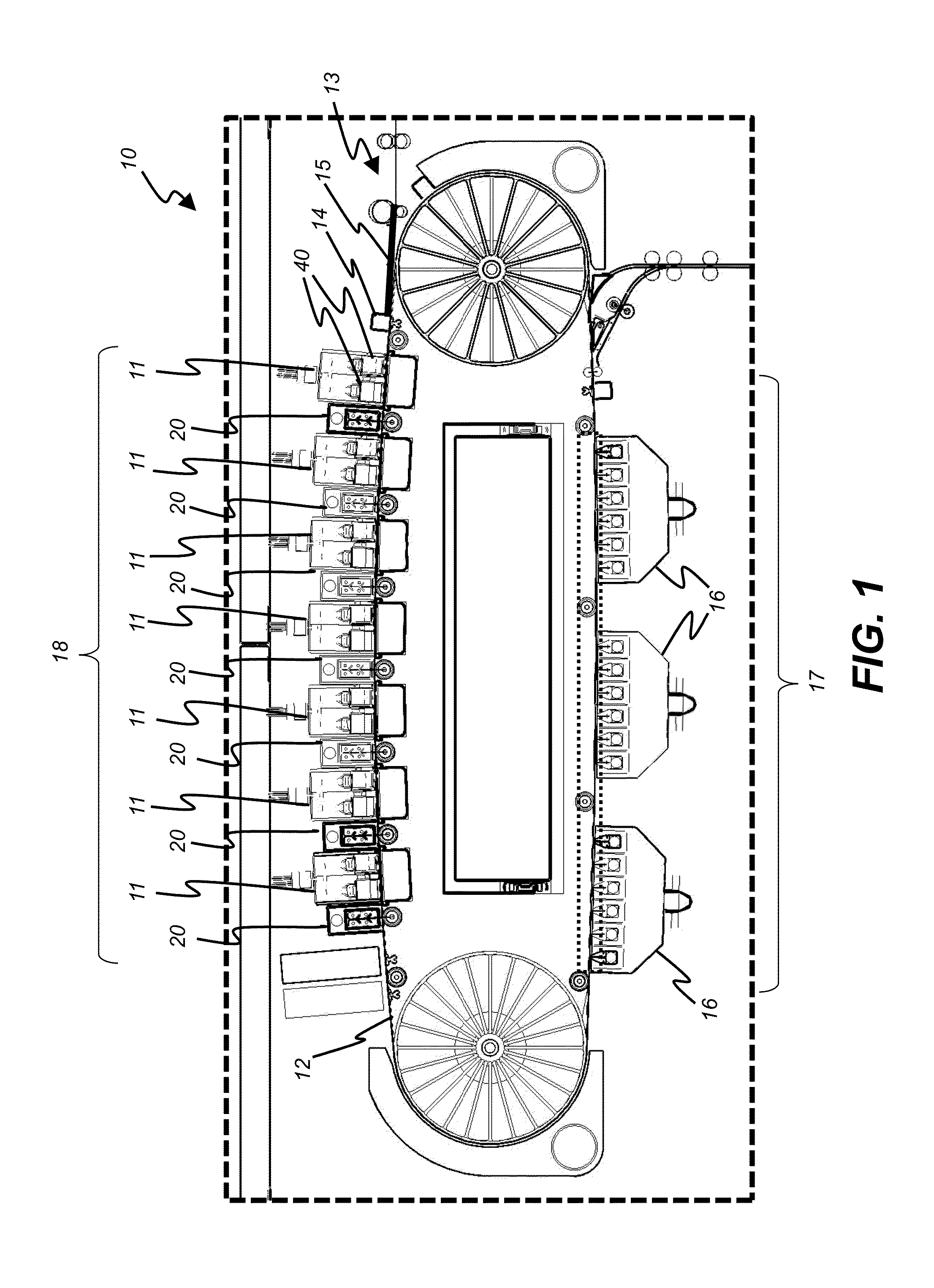
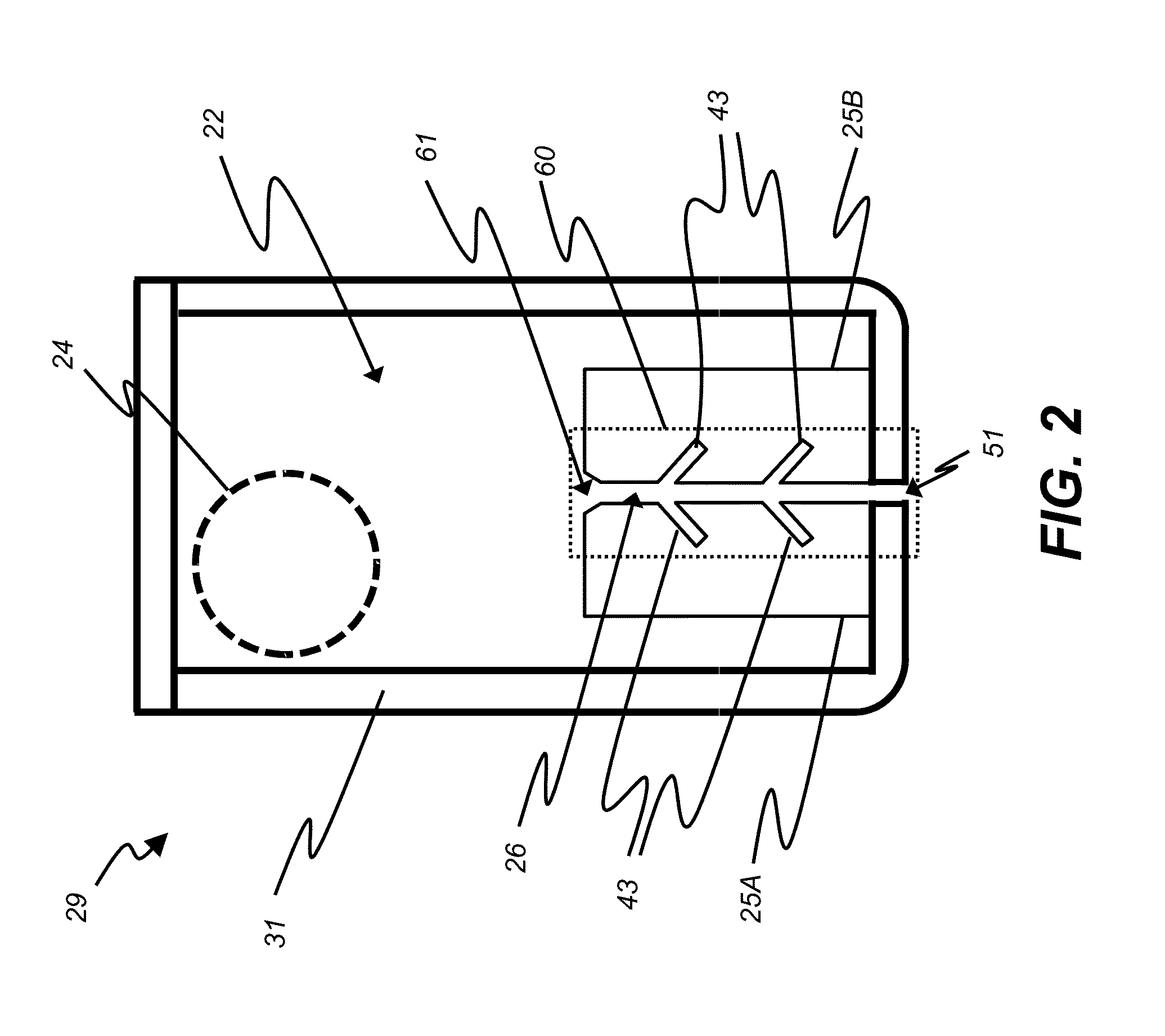
[0013]This invention has the advantage that multiple acoustic air impingement slots can be provided in a small area and with better air flow and drying uniformity than would be possible with equivalent full-crosstrack-width air impingement slots packaged into the same area.
[0014]It has the additional advantage that shorter length acoustic air impingement dryer segments are required. It is easier to maintain the necessary critical dimensions in the shorter acoustic air impingement dryer segments than in full-crosstrack-width air impingement dryers.

Problems solved by technology

Condensation may collect to the point that it forms drops that may fall onto the medium that is being dried, thereby producing coating artifacts or image artifacts that are unacceptable.

Method used


Image

  • Acoustic drying system with interspersed exhaust channels
  • Acoustic drying system with interspersed exhaust channels
  • Acoustic drying system with interspersed exhaust channels

Examples


Embodiment Construction

[0028]The invention is inclusive of combinations of the embodiments described herein. References to “a particular embodiment” and the like refer to features that are present in at least one embodiment of the invention. Separate references to “an embodiment” or “particular embodiments” or the like do not necessarily refer to the same embodiment or embodiments; however, such embodiments are not mutually exclusive, unless so indicated or as are readily apparent to one of skill in the art. The use of singular or plural in referring to the “method” or “methods” and the like is not limiting. It should be noted that, unless otherwise explicitly noted or required by context, the word “or” is used in this disclosure in a non-exclusive sense.

[0029]The present invention will be directed in particular to elements forming part of, or in cooperation more directly with the apparatus in accordance with the present invention. It is to be understood that elements not specifically shown or described m...


PUM


Abstract

An acoustic air impingement drying system is provided for drying a material. An inlet chamber receives air from an airflow source provides air at a supply flow rate. A plurality of acoustic resonant chambers are provided, each having an inlet slot that receives air from the inlet chamber and an outlet slot that directs air onto the material, wherein the acoustic resonant chambers impart acoustic energy to the transiting air, the outlet slots being oriented at an oblique angle relative to the width dimension of the pneumatic transducer unit. A plurality of exhaust air channels interspersed between the outlet slots remove the air directed onto the material by the acoustic resonant chambers. A blower pulls air through the exhaust air channels at an exhaust flow rate.

Description

CROSS-REFERENCE TO RELATED APPLICATIONS[0001]Reference is made to commonly assigned, U.S. patent application Ser. No. 13 / 693,309, now U.S. Pat. No. 8,770,738, entitled: “Acoustic drying system with matched exhaust flow”, by Shifley et al.; and to commonly assigned, co-pending U.S. patent application Ser. No. 13 / 693,366, entitled: “Acoustic drying system with peripheral exhaust conduits”, by Bucks et al., each of which is incorporated herein by reference.FIELD OF THE INVENTION[0002]The present invention relates to the drying of a medium which has received a coating of a liquid material, and more particularly to the use of an air impingement stream and acoustic energy to dry the volatile components of the coating.BACKGROUND OF THE INVENTION[0003]There are many examples of processes where liquid coatings are applied to the surface of a medium, and where it is necessary to remove a volatile portion of the liquid coating by some drying process. The image-wise application of aqueous inks ...

Claims


Application Information

Patent Timeline
Patent Type & Authority Patents(United States)
IPC IPC(8): F26B21/00
CPCF26B21/004
Inventor CIASCHI, ANDREWSHIFLEY, JAMES DOUGLASBUCKS, RODNEY RAYTOMBS, THOMAS NATHANIEL
Owner EASTMAN KODAK CO
Learn More