Method and apparatus for determining optimal image viewing direction

a projection image and viewing direction technology, applied in the field of projection image acquisition and processing methods and apparatuses, can solve the problems of time-consuming processing, inability to perform imaging sessions in real-time, use of these machines during interventions, etc., and achieve the effect of reducing the foreshortening and relevancy of information

Active Publication Date: 2015-09-08
PIE MEDICAL IMAGING
View PDF7 Cites 12 Cited by
  • Summary
  • Abstract
  • Description
  • Claims
  • Application Information

AI Technical Summary

Benefits of technology

[0019]It is thus an object of the present application to provide a method and apparatus for determining optimal image viewing direction in terms of reduced foreshortening and relevancy of information, particularly for clinical interventions.
[0020]It is a further object of the present application to determine such optimal image viewing direction in a manner that reduces the number of acquisitions necessary and thus patient exposure to radiation and contrast agent.
[0029]By automating the determination of the optimal viewing direction in terms of reduced foreshortening as well as relevancy of information, trial and error of different viewing directions is avoided and experience is no longer determinant, which decreases the amount X-ray radiation and of contrast agent needed for obtaining the correct image for the procedure (for those applications requiring usage of contrast agents) and leads to a quicker working time.
[0038]According to another aspect, the present application also relates to an apparatus for acquiring two-dimensional images of a three-dimensional object. The apparatus comprises means for receiving from a user indications on the position of a point or area of interest in at least two two-dimensional images of the object obtained from different perspectives and processing means programmed for performing the method according to the invention to determine a viewing direction for obtaining an optimal image of the object in terms of reduced foreshortening and relevancy of information.

Problems solved by technology

Such apparatus, like CT and MR machines, besides having a large size and thus being cumbersome and expensive, provide a great amount of image data, whose processing is time-consuming and makes it impossible to perform imaging sessions in real-time.
This drawback largely prevents the use of these machines during interventions.
However, such technique can be used only when planning the operation, for example in order to define the size of the valve, since it can be performed neither in real-time nor in a hemodynamic and / or heart surgery room (so called cathlab) during the intervention.
However, two-dimensional projection images, as those obtained with angiographic systems, suffer from the problem of foreshortening.
Foreshortening is the event when an object seems compressed when viewed from a certain perspective, causing distortion of the information.
A large drawback of this approach is that it assumes that every optimal projection contains the same amount of information of the imaged object (that is that the imaged object is symmetrical).
This results in the potential usage of optimal projections that are only suitable for symmetrical objects.
However, as in clinical practice the objects that are dealt with are asymmetrical (see FIG. 1), a recording that is perpendicular to the object does not necessarily contain all the needed information.
This procedure is time consuming and is a burden for the patient because several acquisitions, whether or not supported by administration of a contrast agent, have to be made before the desired optimal view has been found.
Such information varies from case to case and thus cannot be fixed in advance in each imaging procedure.

Method used


Image

  • Method and apparatus for determining optimal image viewing direction
  • Method and apparatus for determining optimal image viewing direction
  • Method and apparatus for determining optimal image viewing direction

Examples


Embodiment Construction

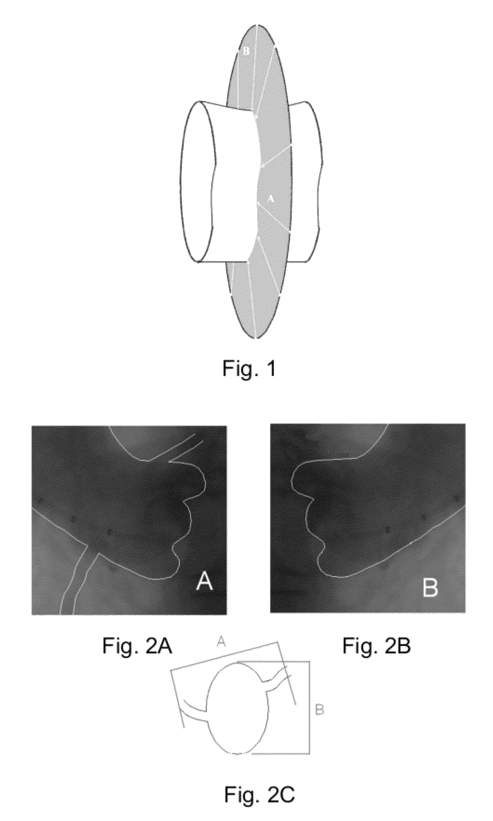
[0059]FIG. 1 shows a tubular organ, like an artery, having an elliptical cross section. All possible optimal projection view directions for this asymmetrical object lie on the indicated grey circle which is perpendicular to the axis of the object. However, as shown in FIGS. 2A and 2B, an optimal projection view direction chosen at point B (FIG. 2B) will contain different object information than an optimal projection view direction chosen from point A (FIG. 2A). Specifically, FIGS. 2A and 2B show the difference in coronary artery visibility in the coronary root when looking from different orthogonal views. In these two figures, FIG. 2A and FIG. 2B, the aortic root (schematically shown in FIG. 2C) is seen from two perspectives. For the view direction of FIG. 2A, the coronary arteries that arise from the aortic root can be seen clearly (see the upper left FIG. 2A. However, for the view direction of FIG. 2B, at the same aortic root both coronary arteries are absent in the image informat...


PUM


Abstract

A computer-implemented method for the determination of the optimal image viewing direction of an asymmetrical object is included. The method generates a 3D surface reconstruction of the object from 2D images of the object obtained from different perspectives. A point of interest can be specified in at least one of the used 2D images and an area of interest can be specified in the object where the point of interest lies within. A plane containing view directions with reduced foreshortening for the specified area of interest is generated and a 3D point corresponding to the specified point of interest is determined on the 3D surface reconstruction of the object. At least one particular view direction corresponding to the 3D point and located with the identified plane is considered as the optimal image viewing direction of the asymmetrical object. A corresponding apparatus and computer program are also disclosed.

Description

CROSS-REFERENCE TO RELATED APPLICATION[0001]This application claims priority from EP 11166739.0 filed on May 19, 2011 and which is hereby incorporated by reference in its entirety.BACKGROUND[0002]1. Field of the Invention[0003]The present invention relates to a method and apparatus for acquiring and processing projection images of an object of interest, particularly angiographic images.[0004]2. State of the Art[0005]During clinical interventions it is important to obtain as much object information as possible to be able to accurately perform a procedure. For this reason the imaging methods usually adopted are those based on the use of apparatus acquiring high resolution volumetric images in order to have a better and more detailed picture of the object under examination.[0006]Such apparatus, like CT and MR machines, besides having a large size and thus being cumbersome and expensive, provide a great amount of image data, whose processing is time-consuming and makes it impossible to ...

Claims


Application Information

Patent Timeline
Patent Type & Authority Patents(United States)
IPC IPC(8): G06T19/00
CPCG06T19/00
Inventor SCHORMANS, RON HUBERTUSREINARTZ, RIANNEABEN, JEAN-PAUL
Owner PIE MEDICAL IMAGING
Why Eureka
Try Eureka