Electronic device that is worn on the wrist

a technology of electronic devices and wrists, applied in protective materials, instruments, horology, etc., can solve the problems of insufficient antenna performance, insufficient reflection of rf signals from ground plates, and inability to achieve good reflection of rf signals, etc., and achieve good reception performance.

Active Publication Date: 2015-09-08
SEIKO EPSON CORP
View PDF24 Cites 5 Cited by
  • Summary
  • Abstract
  • Description
  • Claims
  • Application Information

AI Technical Summary

Benefits of technology

[0010]An electronic device according to the present invention that is worn on the wrist can assure good reception performance.
[0014]In this aspect of the invention the reception unit that processes reception signals based on radio signals received by the antenna is positioned between the information display unit and the back cover, the antenna electrode line is disposed along the outside of the information display unit, and the back cover is made from a conductive material and made to function as a reflection plate that reflects the radio signals. As a result, the information display unit and back cover are separated by some distance because the reception unit is disposed therebetween. The antenna electrode disposed along the outside of the information display unit and the back cover (reflector) are therefore also separated with some distance therebetween, and the reception performance of the antenna can be improved compared with a configuration in which a dial adjacent to the antenna is used as a reflector. In addition, because the back cover functions as a reflector, change in the antenna tuning frequency can be prevented when used in a wristwatch, antenna characteristics can be improved and good reception characteristics can be achieved. More particularly, because the back cover can be easily designed with a relatively large outside dimension, signal reflection efficiency can be easily improved, and antenna characteristics can be easily improved.
[0016]This aspect of the invention can more efficiently reflect signals off the back cover, which is larger than the outside dimension of the antenna electrode, and thus improve the reception strength entering the antenna electrode.
[0018]In this aspect of the invention, because the antenna is disposed between a dial ring and a bezel that are ring shaped and made from a non-conductive material, good reception performance can be achieved because signals are not blocked, and impairment of the appearance can be prevented because the antenna is covered by the dial ring and bezel and is not exposed to the outside.
[0025]In this aspect of the invention, reception signals based on the signals received by the main antenna unit disposed on the top side of the dielectric substrate are transmitted from the power supply unit that branches from the main antenna unit through the connection member to the reception unit. As a result, reception signals extracted from the received signals can be suitably transmitted to the reception unit by means of a simple configuration such as rendering a through-hole that passes the connection member through without the connection member touching other conductive parts.
[0029]If the antenna electrode is disposed around the outside of a dial or display panel made from such non-conductive materials, reception characteristics are not impaired and good reception performance can be achieved.

Problems solved by technology

A problem with the configurations taught in both JP-A-2000-59241 and JP-A-2000-59241 is that sufficient antenna performance cannot be assure.
More particularly, the problem with the configurations taught in JP-A-2000-59241 and JP-A-2000-59241 is that the antenna and the ground plate (the metal base or the dial) are too close together, good reflection of RF signals from the ground plate is not achieved, and sufficient antenna performance cannot be obtained.

Method used


Image

  • Electronic device that is worn on the wrist
  • Electronic device that is worn on the wrist
  • Electronic device that is worn on the wrist

Examples


embodiment 1

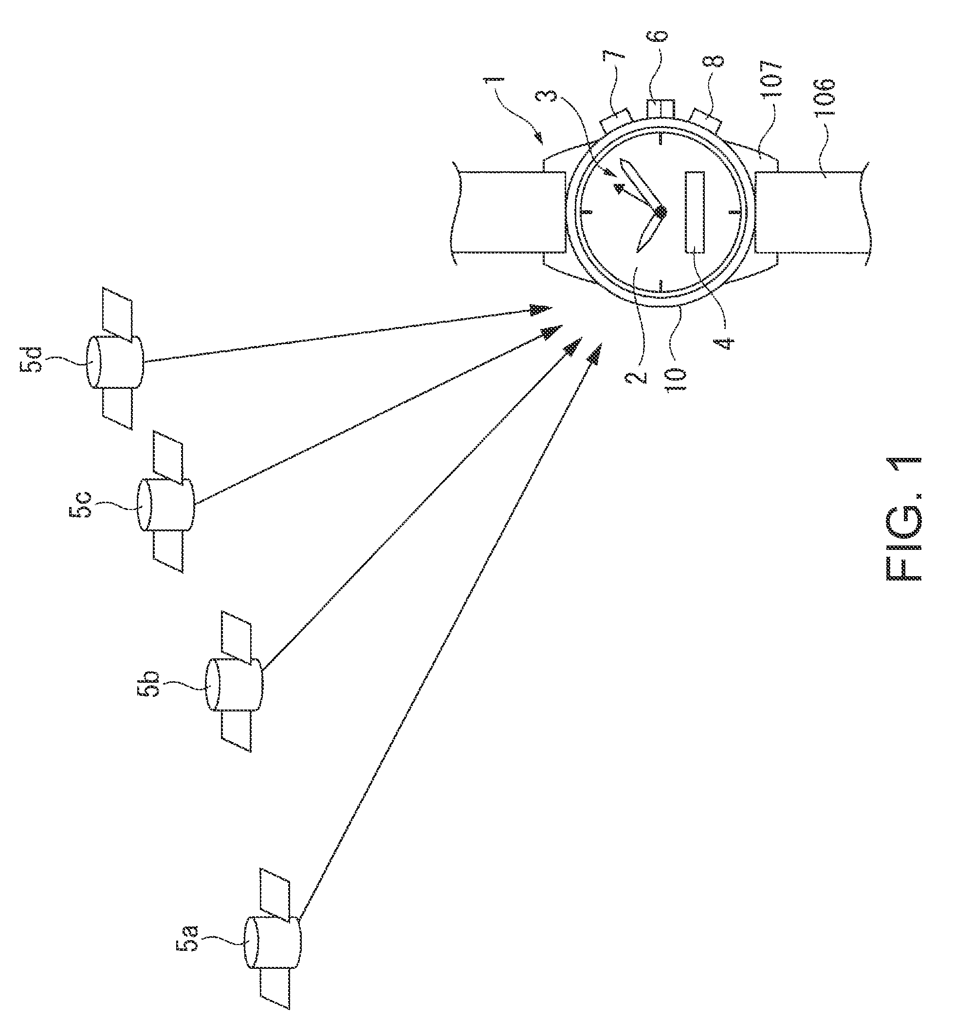
[0042]A first embodiment of the invention is described below with reference to the accompanying figures.

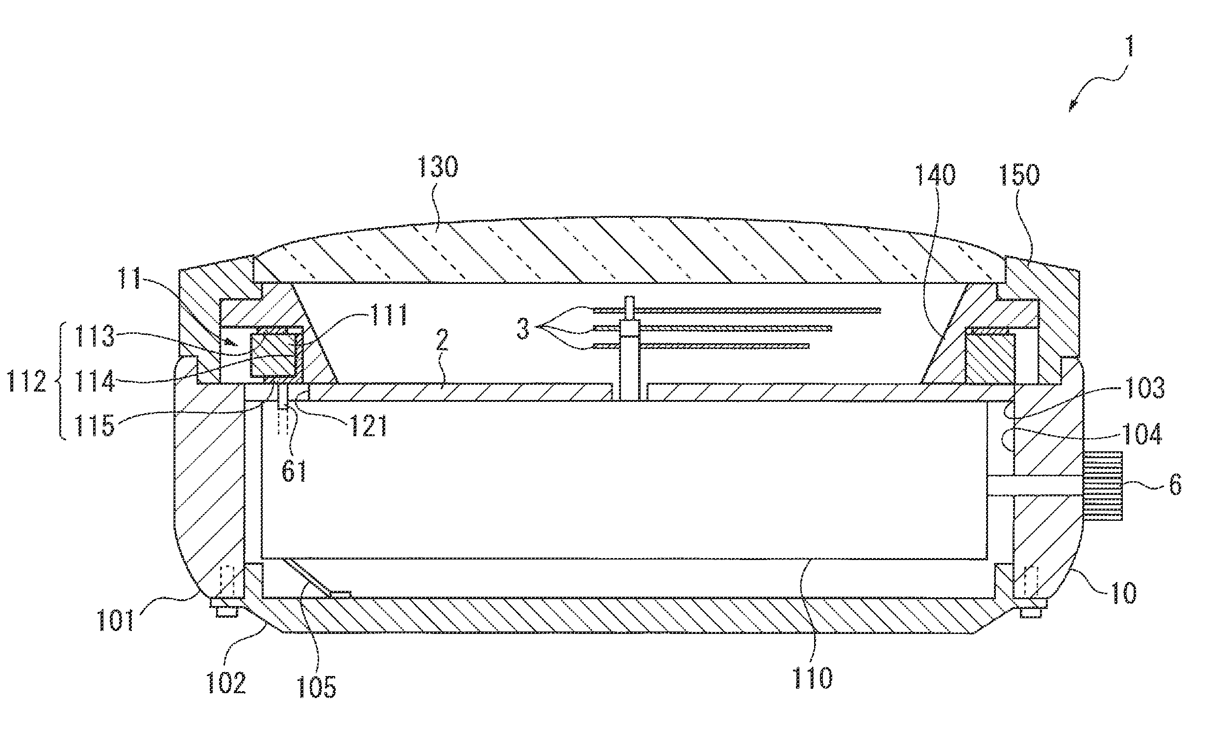
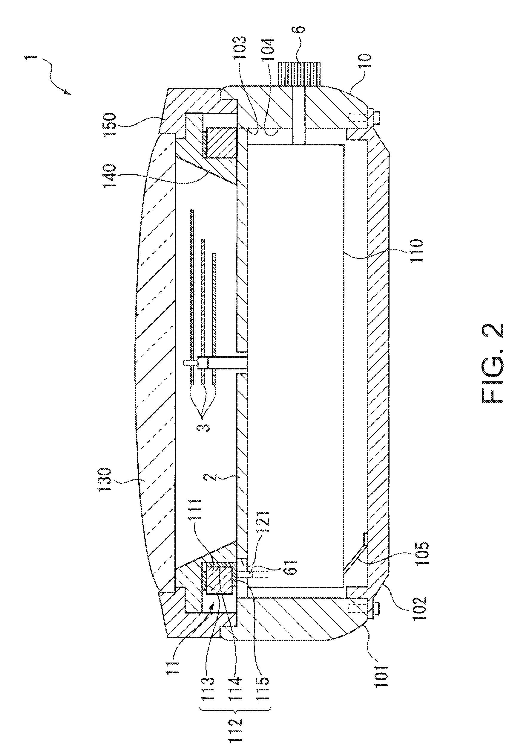
[0043]As shown in FIG. 1, an electronic device 1 according to the first embodiment of the invention is worn on the wrist, and more specifically is an electronic timepiece that is worn on the wrist and has a time display unit for displaying time by means of a dial 2 and hands 3 as information display units.

[0044]The dial 2 is made with a disk shape from an electrically non-conductive material such as plastic or a ceramic that affords a high quality appearance. A window is formed in a part of the dial 2, and an LCD display panel or other type of display 4 is presented in this window as an information display unit.

[0045]The hands 3 include a second hand, minute hand, and hour hand, and are driven through a drive mechanism including a stepper motor and wheel train as described below. Note that because the area of the hands 3 is small, they do not interfere with radio signal reception ...

embodiment 2

[0151]A second embodiment of the invention is described next with reference to the accompanying figures.

[0152]This second embodiment of the invention displays the time using a liquid crystal display device instead of displaying the time using a dial 2 as described in the first embodiment.

[0153]FIG. 7 is a schematic section view of a electronic device 1 according to the second embodiment of the invention. Note that like parts in this embodiment and the first embodiment are identified by the same reference numerals in the figures, and further description thereof is omitted.

[0154]The case 10 in this second embodiment of the invention includes a cylindrical external case member 101 made from an electrically non-conductive material and a round back cover 102 that covers one of the openings in the case member 101 (the opening on the bottom side as seen in FIG. 7).

[0155]A module 110 that has an LCD panel 17, which is a display panel used as a flat information display unit for displaying th...

embodiment 3

[0164]A third embodiment of the invention is described next with reference to the accompanying figures.

[0165]This third embodiment of the invention uses an electrically conductive cover member 101A instead of the electrically non-conductive case member 101 of the first embodiment.

[0166]FIG. 8 is an exploded oblique view of a electronic device 1 according to the third embodiment of the invention.

[0167]The case 10 according to the third embodiment of the invention has a case member 101 of which part is made from an electrically non-conductive material.

[0168]This case member 101 includes a cover member 101A made from a conductive material (such as stainless steel or other metal), and a non-conductive case ring 101B that is disposed inside the cover member 101A. The surface of the case ring 101B is coated with a metallic coating to match the appearance of the metal cover member 101A.

[0169]A conductive back cover 102 is disposed to one of the openings in the case member 101, and more spe...


PUM


Abstract

A wrist-worn electronic device includes an antenna that receives externally transmitted radio signals; a case of which at least part is made of a non-conductive material; an information display unit that is housed inside the case, is flat, and is made of a non-conductive material; a back cover that is attached to the case and is made of a conductive material; and a reception unit that is positioned and housed inside the case between the information display unit and the back cover, and processes a reception signal based on radio signals received by the antenna. The antenna has an antenna electrode that is disposed and formed as a line around the outside of the information display unit. The back cover is connected to the ground potential of the reception unit and reflects the radio signals.

Description

CROSS-REFERENCE TO RELATED APPLICATION(S)[0001]The entire disclosure of Japanese Patent Application No. 2009-250631, filed Oct. 30, 2009, is expressly incorporated by reference herein.BACKGROUND[0002]1. Technical Field[0003]The present invention relates to an electronic device that is worn on the wrist and has a built-in antenna for receiving radio signals that include time information and are transmitted from an external source.[0004]2. Related Art[0005]Electronic timepieces that have a wireless communication function have been available for some time. One use for this wireless communication function is to receive signals from a positioning information satellite, such as a GPS (Global Positioning System) satellite, and acquire the current time from the received satellite signal.[0006]When a radio capability is rendered in a wristwatch as an example of an electronic timepiece with a radio function, an antenna that can provide satisfactory performance in a confined space is essential...

Claims


Application Information

Patent Timeline
Patent Type & Authority Patents(United States)
IPC IPC(8): H01Q1/12G04B47/00G04G5/00G04G21/04G04R20/02G04R60/10G04R60/12H01Q1/24H01Q1/27H01Q1/40H01Q1/44H01Q7/00H01Q19/13
CPCH01Q1/273G04G5/002G04R60/10H01Q1/40H01Q7/00
Inventor FUJISAWA, TERUHIKO
Owner SEIKO EPSON CORP
Why Eureka
Try Eureka