Image forming apparatus capable of reliably protecting exposure member

a technology of exposure member and forming apparatus, which is applied in the direction of electrographic process apparatus, instruments, optics, etc., can solve the problems of insufficient mechanical strength of led array, user's accidental touch of led array, and damage to led array through led cover

Inactive Publication Date: 2015-09-15
BROTHER KOGYO KK
View PDF18 Cites 6 Cited by
  • Summary
  • Abstract
  • Description
  • Claims
  • Application Information

AI Technical Summary

Benefits of technology

[0008]In the former printer, when the developing drawer is detached, the LED array is separated away from the photosensitive drum and then the developing drawer is withdrawn. Hence, sliding friction of the LED array with respect to the photosensitive drum and contact thereof with other members can be prevented. However, the LED array is exposed after the developing drawer is withdrawn, so that a user may accidentally touch the LED array to damage or soil the same.
[0009]Further, in the latter printer, by covering the LED array with the LED cover when separating the photosensitive drum away from the LED array, the LED array can be protected. However, the LED cover covers the LED array through the pivotal movement thereof, so that a mechanical strength thereof is insufficient. Thus, if the developing cartridge interferes with the LED cover when being attached to the process unit, the LED array may be damaged through the LED cover.
[0010]In view of the foregoing, it is an object of the present invention to provide an image forming apparatus capable of reliably protecting an exposure member and ensuring reliability of the image forming apparatus over a prolonged period of time.

Problems solved by technology

However, the LED array is exposed after the developing drawer is withdrawn, so that a user may accidentally touch the LED array to damage or soil the same.
However, the LED cover covers the LED array through the pivotal movement thereof, so that a mechanical strength thereof is insufficient.
Thus, if the developing cartridge interferes with the LED cover when being attached to the process unit, the LED array may be damaged through the LED cover.

Method used


Image

  • Image forming apparatus capable of reliably protecting exposure member
  • Image forming apparatus capable of reliably protecting exposure member
  • Image forming apparatus capable of reliably protecting exposure member

Examples


second embodiment

8. Second Embodiment

[0221](1) Structure of Printer According to Second Embodiment

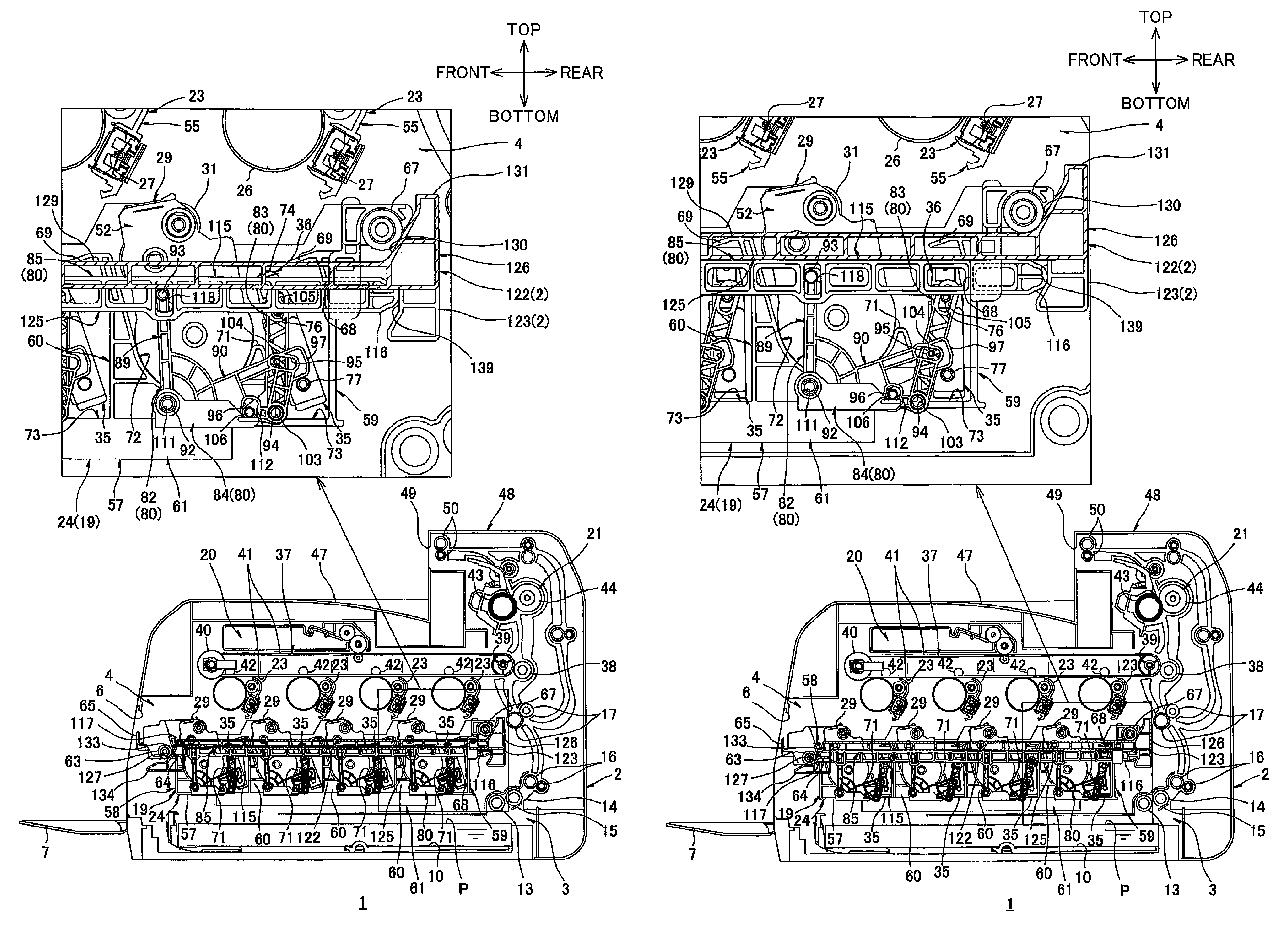
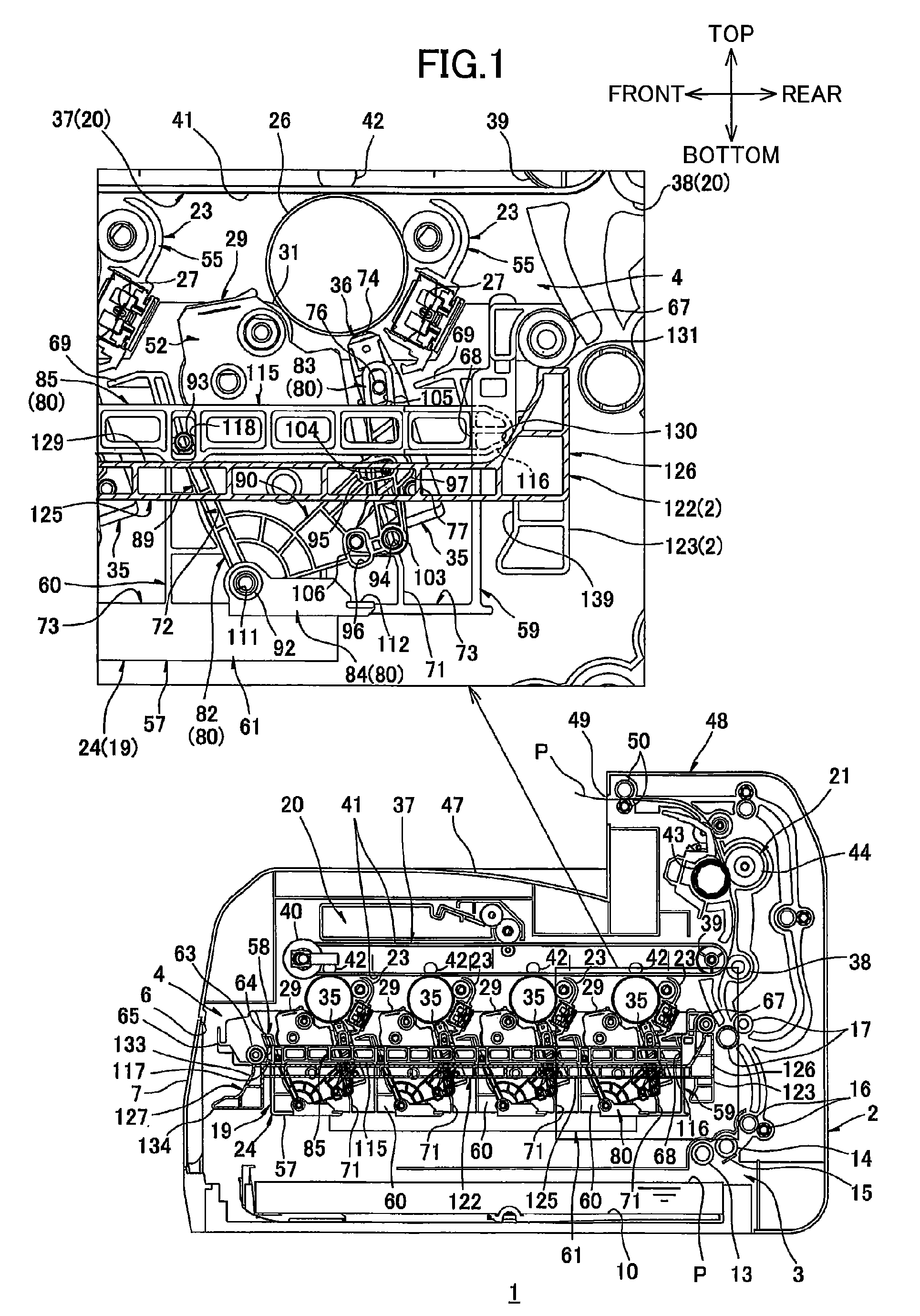
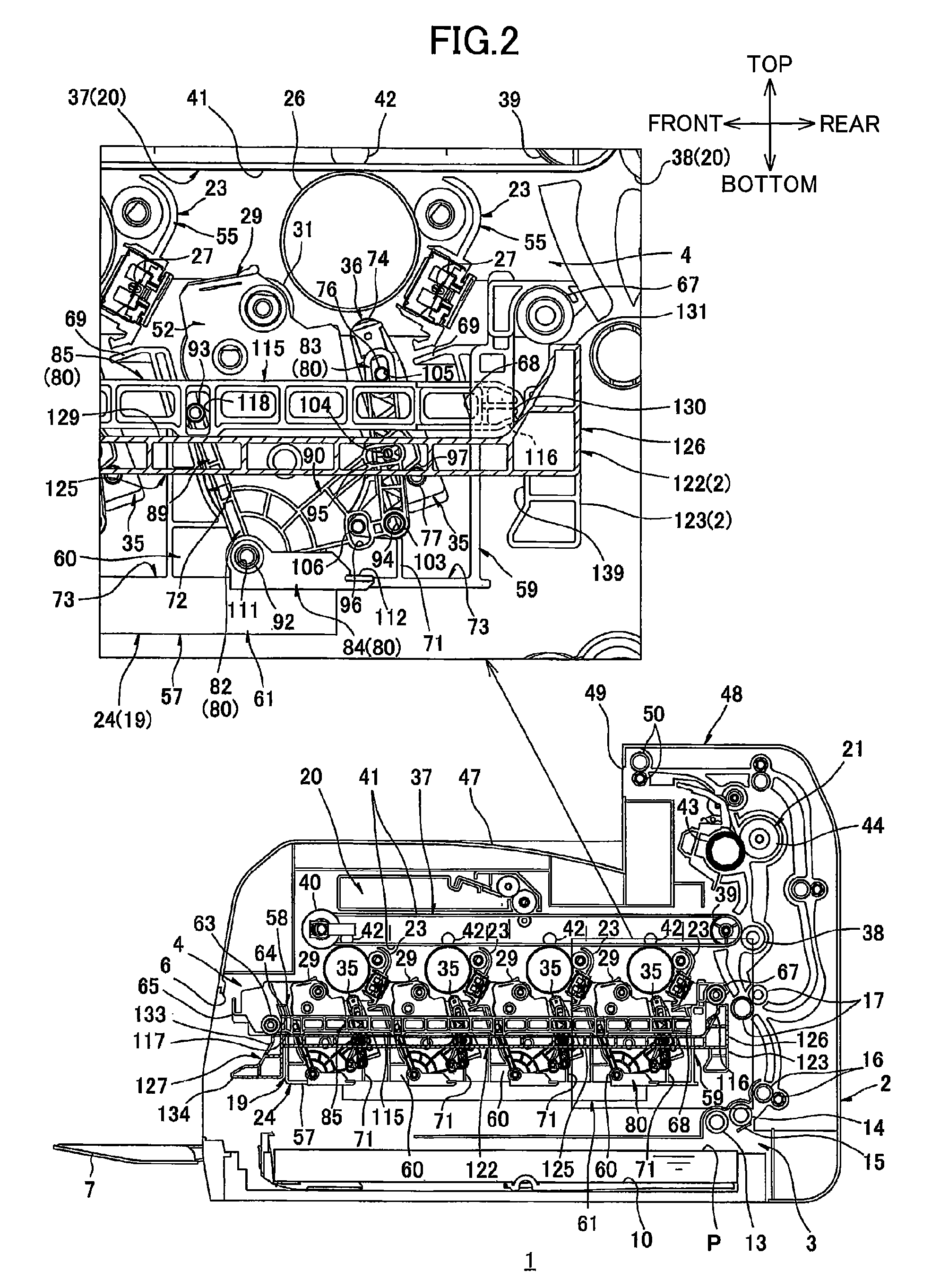
[0222]A printer 201 as an image forming apparatus according to a second embodiment of the present invention will be described while referring to FIGS. 7 through 9, wherein like parts and components are designated with the same reference numerals to avoid duplicating description. In the following description, only parts differing from those of the first embodiment will be described in detail.

[0223]In the above-described first embodiment, the image forming unit 4 includes the process unit 19 at substantially the vertical center region of the main casing 2, as illustrate in FIG. 1. Further, the process unit 19 includes the plurality of drum units 23 and the developing drawer 24.

[0224]Each drum unit 23 is provided in the main casing 2 so as not to be movable relative to the main casing 2. The developing drawer 24 includes the plurality of developing units 29 and the plurality of LED units 35. The plurality ...


PUM


Abstract

An image forming apparatus includes: a main casing; a photosensitive member; a moving mechanism; a movable member; and a cartridge. The photosensitive member is provided in the main casing. The movable member moves between an inside position in which the movable member is inside the main casing and an outside position in which the movable member is at least partly outside the main casing. The movable member includes: a frame; a protection member; and an exposure member. The protection member is fixed to the frame. The moving mechanism moves the exposure member between an exposing position in which the exposure member exposes the photosensitive member to light and a protected position in which the exposure member is protected by the protection member. The cartridge includes a developer bearing member. The cartridge is supported at the movable member.

Description

CROSS REFERENCE TO RELATED APPLICATION[0001]This application claims priority from Japanese Patent Application No. 2013-015318 filed Jan. 30, 2013. The entire content of the priority application is incorporated herein by reference.TECHNICAL FIELD[0002]The present invention relates to an image forming apparatus using an electrophotographic method.BACKGROUND[0003]There is known, as an image forming apparatus, a printer provided with a plurality of photosensitive drums and a plurality of exposure members for exposing the corresponding photosensitive drums.[0004]There is proposed, as such a printer, one detachably provided with a drum drawer having a plurality of photosensitive drums; and a developing drawer having a plurality of developing units and a plurality of LED units.[0005]In the printer of such a type, when the drum drawer and the developing drawer are detached from the printer, first the developing drawer is moved in a direction away from the dram drawer, i.e., in such a direct...

Claims


Application Information

Patent Timeline
Patent Type & Authority Patents(United States)
IPC IPC(8): G03G15/00G03G21/18G03G21/16
CPCG03G21/1666G03G21/1832G03G2221/1636G03G21/1623
Inventor KATO, ATSUSHIFURUKAWA, TOSHIO
Owner BROTHER KOGYO KK
Why Eureka
Try Eureka