Detecting the locations of a plurality of objects on a touch surface

a technology of touch surface and location, applied in the direction of instruments, computing, electric digital data processing, etc., can solve the problems of increasing the energy consumption of illuminating the panel, not readily scalable, and the cost of known ftir techniques,

Inactive Publication Date: 2015-09-15
FLATFROG LAB
View PDF64 Cites 34 Cited by
  • Summary
  • Abstract
  • Description
  • Claims
  • Application Information

AI Technical Summary

Problems solved by technology

These known FTIR techniques suffer from being costly, i.a. since they require the use of a large number of detectors, and possibly a large number of light sources.
Furthermore, they are not readily scalable since the required number of detectors / sources increases significantly with the surface area of the panel.
Still further, the energy consumption for illuminating the panel may be considerable and increases significantly with increasing surface area of the panel.

Method used


Image

  • Detecting the locations of a plurality of objects on a touch surface
  • Detecting the locations of a plurality of objects on a touch surface
  • Detecting the locations of a plurality of objects on a touch surface

Examples


Embodiment Construction

[0073]The present invention relates to techniques for detecting locations of a plurality of points-of-touch on a surface of a radiation transmissive panel. For ease of understanding, some underlying principles will first be discussed in relation to a simplified example, before describing exemplifying beam arrangements for multi-touch detection. Then, examples of system configurations are given, followed by a number of detailed implementation examples in relation to one such system configuration. The description is concluded by a data processing example. Throughout the description, the same reference numerals are used to identify corresponding elements.

General

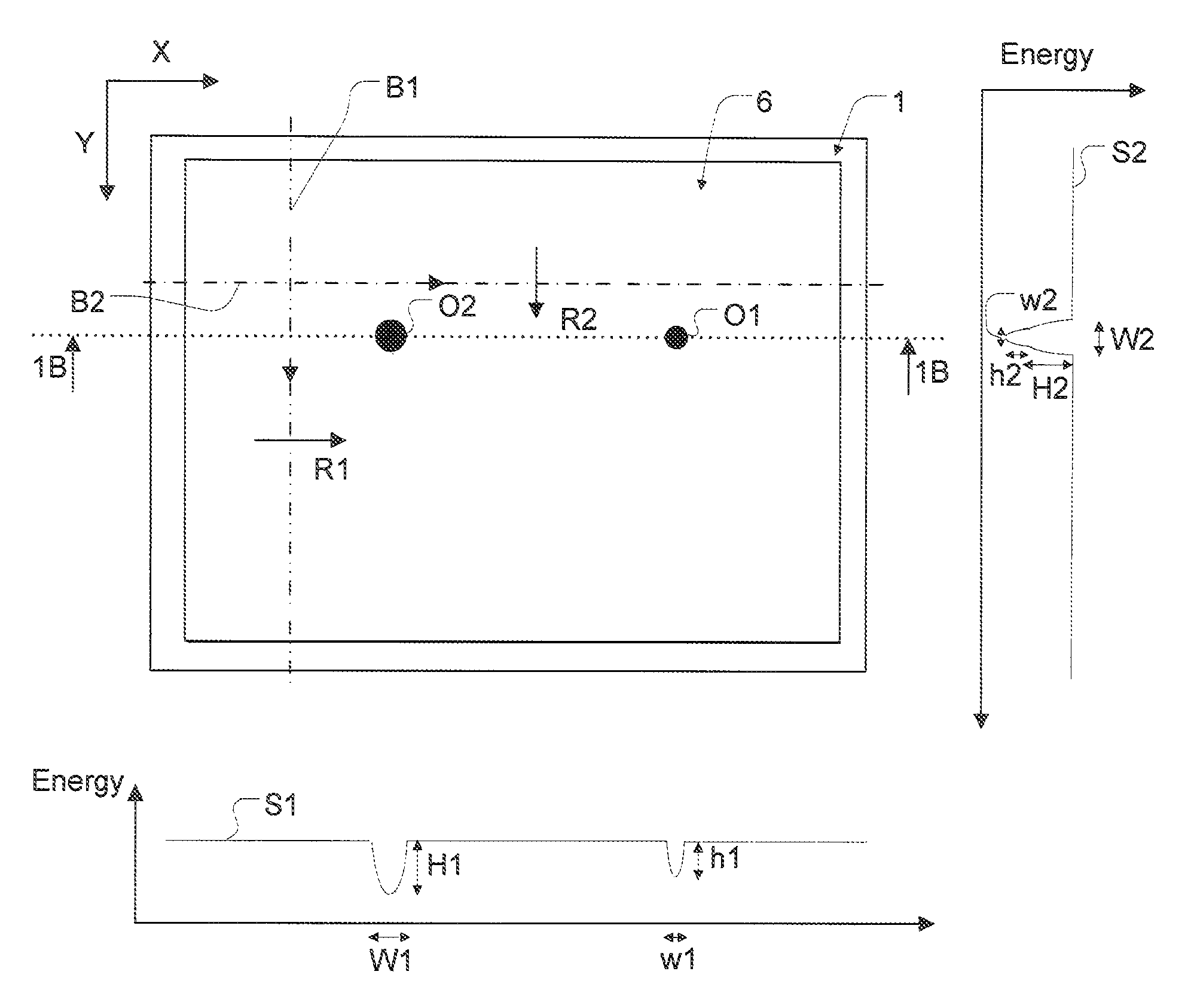
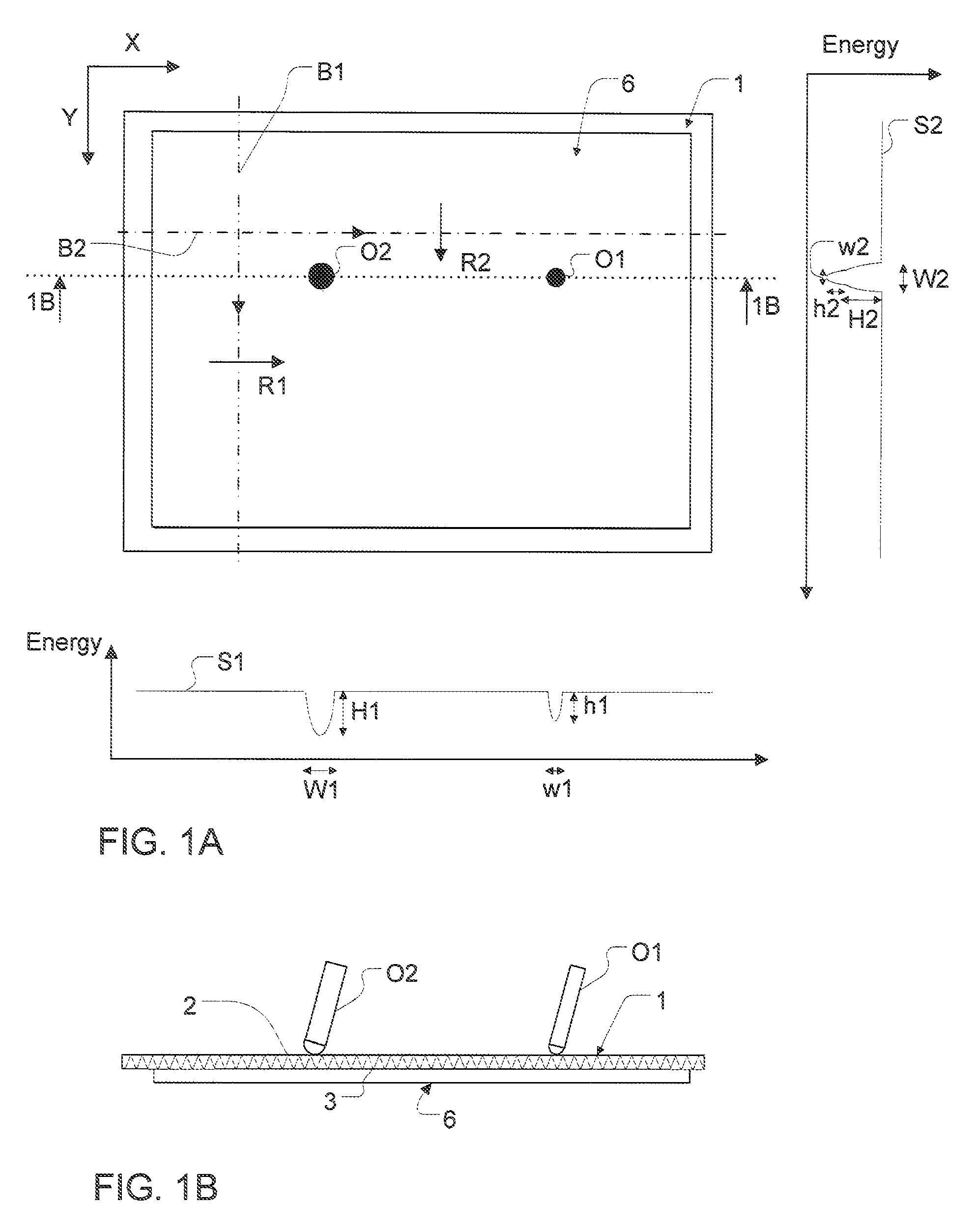
[0074]An example of a touch-sensing system including a radiation-transmissive panel 1 is shown in the top plan view of FIG. 1A and the section view of FIG. 1B (taken along line 1B-1B in FIG. 1A). The panel 1 defines two opposite and generally parallel surfaces 2, 3 and may be planar or curved. The panel 1 is configured to allow ...


PUM


Abstract

An apparatus is controlled to detect locations of a plurality of objects on a touch surface of a panel. An input scanner arrangement introduces at least three beams of radiation into the panel for propagation by internal reflection, and sweeps the beams inside the panel across a sensing area, preferably in at least two different principal directions. At least one radiation detector is arranged to receive the beams from the input scanner arrangement while they are swept across the sensing area. A data processor is connected to the radiation detector(s) and operated to identify the locations based on an attenuation of the beams caused by the objects touching the touch surface within the sensing area, the attenuation being identifiable from an output signal of the radiation detector(s). Each output signal may be further processed to generate a transmission signal, by dividing the output signal by a background signal which represents the output signal without any object on the touch surface.

Description

CROSS-REFERENCE TO RELATED APPLICATIONS[0001]The present application claims the benefit of Swedish patent application No. 0801466-4, filed on Jun. 23, 2008, and U.S. provisional application No. 61 / 129,373, filed on Jun. 23, 2008, both of which are incorporated herein by reference.TECHNICAL FIELD[0002]The present invention relates to techniques for detecting the locations of a plurality of objects on a touch surface. The touch surface may be part of a touch-sensitive panel.BACKGROUND ART[0003]To an increasing extent, touch-sensitive panels are being used for providing input data to computers, electronic measurement and test equipment, gaming devices, etc. The panel may be provided with a graphical user interface (GUI) for a user to interact with using e.g. a pointer, stylus or one or more fingers. The GUI may be fixed or dynamic. A fixed GUI may e.g. be in the form of printed matter placed over, under or inside the panel. A dynamic GUI can be provided by a display screen integrated w...

Claims


Application Information

Patent Timeline
Patent Type & Authority Patents(United States)
IPC IPC(8): G06F3/042
CPCG06F3/0421G06F3/0423G06F2203/04109G06F3/042
Inventor WASSVIK, OLACHRISTIANSSON, TOMAS
Owner FLATFROG LAB
Why Eureka
Try Eureka