Joint motion facilitation device

a joint motion and facilitation device technology, applied in the field of joint motion facilitation devices, can solve the problems of inability to provide flexion and extension motion of several fingers by a single actuator, inability to provide motion for all joints of a plurality of fingers, and inability to achieve the effect of providing motion for several fingers in a single manner,

Active Publication Date: 2015-09-22
YAMAMOTO KEIJIROU
View PDF18 Cites 4 Cited by
  • Summary
  • Abstract
  • Description
  • Claims
  • Application Information

AI Technical Summary

Benefits of technology

[0023]As has been explained above, according to the joint motion facilitation device of the present invention, the advantageous effects are obtained that, along with easy fitting being possible, it is also possible to facilitate sufficient joint motion for each joint.
are obtained that, along with easy fitting being possible, it is also possible to facilitate sufficient joint motion for each joint.

Problems solved by technology

The use of a single actuator in this manner for providing motion for all of the joints of a plurality of fingers is not really a method well adapted for providing flexion and extension motion of several fingers.
In particular, since the joints of the thumb flex around rotational axes whose directions are different from those of the joints of the other four fingers, with the technique of this prior art example, not only is it not possible to facilitate joint motion of the thumb, but also it is possible that force may be exerted in an improper direction that is different from the direction of thumb flexion.
Furthermore since the technique of the prior art example is adapted for the fingers to be inserted into the device in the state in which the fingers are extended, for a patient for whom opening and closing his fingers by his own efforts is difficult, such as a patient who has already suffered finger contracture or the like, it becomes difficult to put his fingers into the device.
Yet further, with the technique of the prior art example, if the amount of pressure reduction in the closed chamber is insufficient, then the limits for joint motion become restricted, and sufficient joint motion cannot be obtained.

Method used


Image

  • Joint motion facilitation device
  • Joint motion facilitation device
  • Joint motion facilitation device

Examples


Embodiment Construction

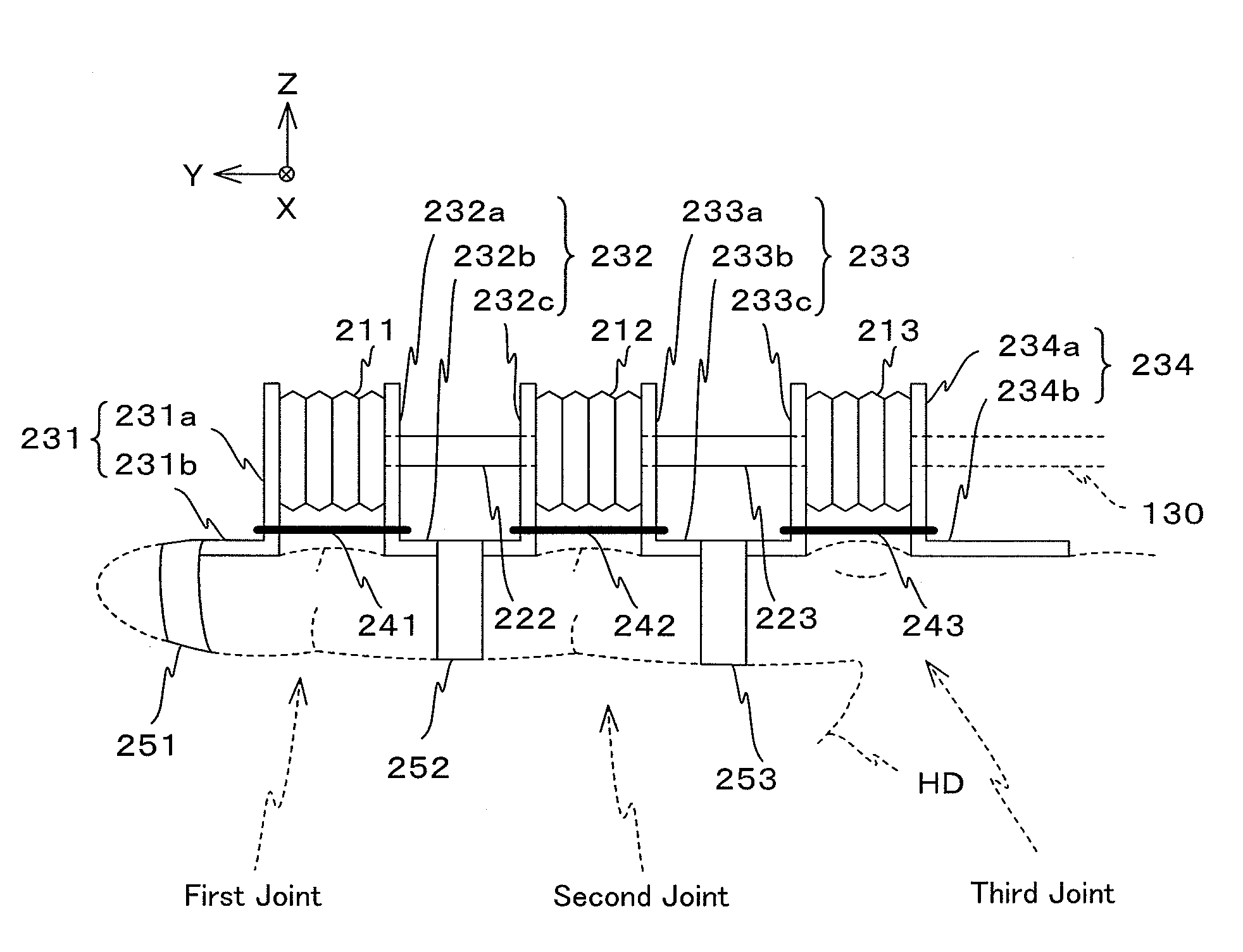
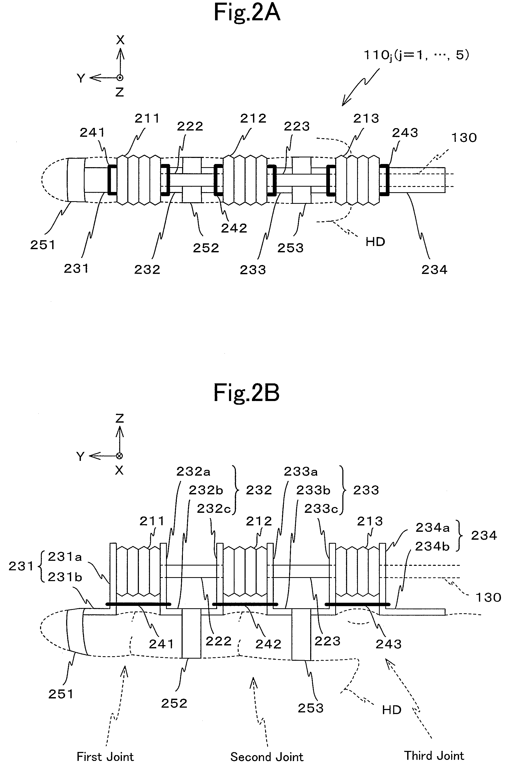
[0049]In the following, an embodiment of the present invention will be explained with reference to FIGS. 1 through 8A and 8B. It should be understood that, in this embodiment, as an example, a joint motion facilitation device that facilitates joint motion of the fingers and wrist of the right hand of the body of a human subject, which is the predetermined subject body portion in this case, will be explained. Moreover, in the following explanation and drawings, the same reference symbols are appended to elements that are the same or equivalent, and duplicated explanation is omitted.

[Structure]

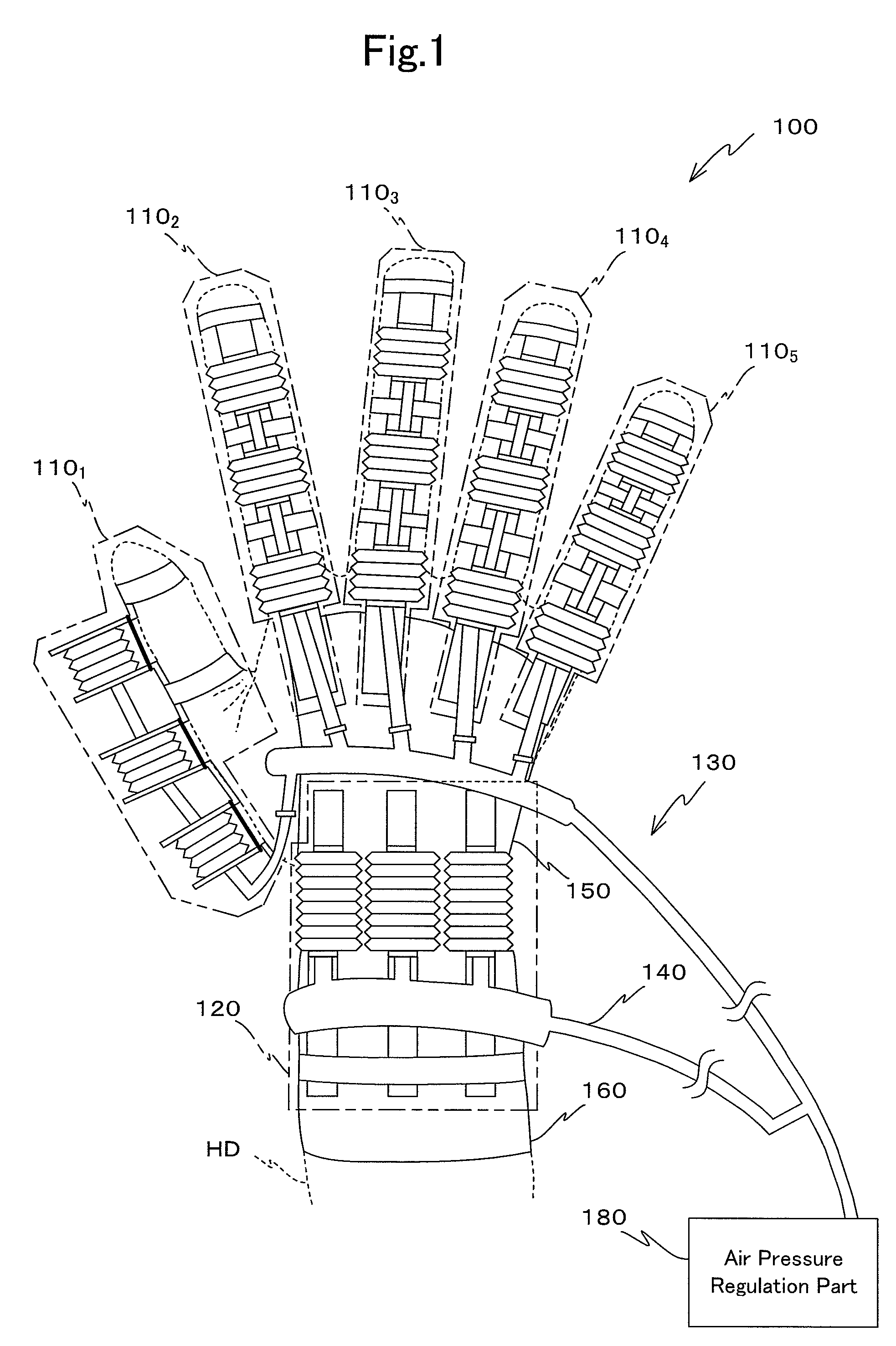
[0050]FIG. 1 is a figure showing the external appearance of a joint motion facilitation device 100 that is an embodiment. FIG. 1 is a figure showing the external appearance of the joint motion facilitation device 100 that is installed to a hand HD of the body of a human subject, as viewed from the hand rear (i.e. the back of the hand) when the joints of the fingers and the wrist are in the exten...


PUM


Abstract

When air is supplied by an air pressure regulation part to bellows 211 through 213 of finger joint motion facilitation parts 110j (where j=1, . . . , 5), the bellows 211 through 213 expand approximately in the shape of circular arcs, since annular grooves on the side of the bellows 211 through 213 opposing a joint are elastically restrained by elastic members 241 through 243. Due to this, the bellows 211 through 213 cooperate, and exert force in the rotational direction to flex the first through the third joints of a finger from their extended states. Next, when air is exhausted from the bellows by the air pressure regulation part, the bellows 211 through 213 contract. Due to this, the bellows 211 through 213 cooperate, and exert force in the rotational direction to extend the first through the third joints of a finger from their flexed states. The forces generated in this manner are transmitted to the joints by transmission members 231 through 234. As a result mounting becomes simple, and also it is possible to facilitate sufficient joint movement for each joint.

Description

RELATED APPLICATION[0001]This is a continuation application of the international patent application No. PCT / JP2010 / 058013 filed with Application date: May 12, 2010. The present application is based on, and claims priority from, J.P. Application 2009-231532, filed on Oct. 5, 2009, the disclosure of which is hereby incorporated by reference herein its entirety.BACKGROUND OF THE INVENTION[0002]The present invention relates to a joint motion facilitation device, and more particularly relates to a joint motion facilitation device that facilitates joint motion of a predetermined subject body portion.BACKGROUND ART[0003]From the past, devices of various kinds have been introduced for use in rehabilitation. Among devices of this type, there are ones that replace a physiotherapist in facilitation treatment with physical exercises and motion, with the goal of recovery of the fundamental operation of the patient.[0004]One such device that facilitates motion of the patient is a device that faci...

Claims


Application Information

Patent Timeline
Patent Type & Authority Patents(United States)
IPC IPC(8): A61H1/00A61H1/02
CPCA61H1/02A61H1/0237A61H1/0262A61H1/0274A61H2201/5056
Inventor YAMAMOTO, KEIJIROU
Owner YAMAMOTO KEIJIROU
Why Eureka
Try Eureka