Catheter assembly and method of treating a vascular disease
a catheter and vascular disease technology, applied in the field of catheter assembly, can solve the problems of energy from the energy delivery device destroying the tissue of the vein
- Summary
- Abstract
- Description
- Claims
- Application Information
AI Technical Summary
Benefits of technology
Problems solved by technology
Method used
Image

Examples
second embodiment
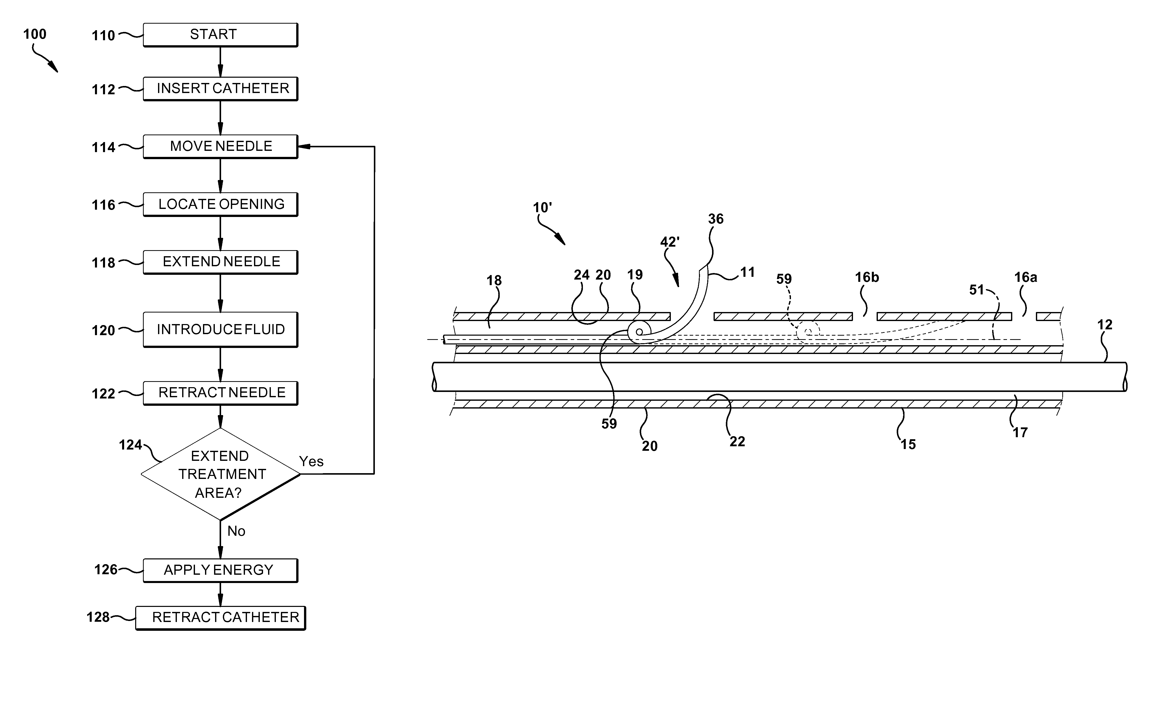
[0044]Although the distal end portion 42 of the needle 11 is shown in FIGS. 1-2 as having a predetermined smoothly curved configuration and as projecting radially outwardly, the distal end portion may have other predetermined configurations. For example, FIG. 4 shows a catheter assembly 10′ in accordance with the present invention, in which the distal end portion 42′ of the needle 11 includes a coil 59 that is axially spaced from the distal tip 36 of the needle. The coil 59 acts as a spring to increase the radial bias or resilience in a radial direction of the distal end portion 42′ of the needle 11 and thereby increase the force with which the distal end portion can penetrate vascular tissue, as well as tissue outside of and surrounding vascular tissue. The distal end portion 42 of the needle 11 may have still other predetermined configurations, such as an angled configuration, and may project from the catheter 15 in other directions, such as ninety degrees or another angle from th...
third embodiment
[0045]As a further alternative, one of the first and second lumens 17 and 18 of the catheter 15 shown in FIGS. 1-2 could be eliminated. FIG. 5 illustrates a catheter assembly 10″, in accordance with the present invention. The catheter assembly 10″ is similar in construction to the catheter assembly 10 but the catheter 15″ of the catheter assembly 10″ includes only a single catheter lumen. More particularly, the sheath or catheter 15″ includes a catheter wall 19″ and a single catheter lumen 60 extending lengthwise of the catheter wall. The catheter wall 19″ is made of two coaxial layers of different materials. The radially inner layer 62 is formed of coiled or braided strands of a bio-compatible metallic or polymeric material. The radially outer layer 64 is formed of a homogeneous mass of a flexible bio-compatible material, such as a medical grade polymer or a medical grade elastomer.
[0046]The inner layer 62 of the catheter wall 19″ provides additional column strength to the catheter...
fourth embodiment
[0079]As yet another alternative, the needles 11 and 11″, which are deployed from inside the catheter walls 19 and 19″, respectively, can be replaced with one or more needles that are deployed from outside of a catheter wall. FIGS. 6 and 6A illustrate a catheter assembly 300, in accordance with the present invention. The catheter assembly 300 includes a sheath or catheter 302, which is made of a flexible and resilient bio-compatible material, such as a medical grade elastomer. The catheter 302 includes a catheter wall 304 and a lumen 306 extending lengthwise of the catheter wall.
[0080]The catheter wall 304 includes a radially outer surface 308 and a radially inner surface 310. The inner surface 310 at least partially defines the lumen 306. The outer surface 308 and the inner surface 310 are free of ports or openings that extend from the outer surface to the inner surface. The outer surface 308 does, however, include a longitudinally extending groove 312. The inner surface 310 and th...
PUM
 Abstract
Description
Claims
Application Information
 - R&D
- Intellectual Property
- Life Sciences
- Materials
- Tech Scout
- Unparalleled Data Quality
- Higher Quality Content
- 60% Fewer Hallucinations
Browse by: Latest US Patents, China's latest patents, Technical Efficacy Thesaurus, Application Domain, Technology Topic, Popular Technical Reports.
© 2025 PatSnap. All rights reserved.Legal|Privacy policy|Modern Slavery Act Transparency Statement|Sitemap|About US| Contact US: help@patsnap.com