Unlock instant, AI-driven research and patent intelligence for your innovation.
Valve assembly intended for use together with a pallet container and a liner
What is Al technical title?
Al technical title is built by PatSnap Al team. It summarizes the technical point description of the patent document.
a pallet container and valve assembly technology, applied in the direction of valve details, lift valves, closures, etc., can solve the problems of putting some demands on the material used, virtually impossible material recovery,
Inactive Publication Date: 2015-09-22
SCHOELLER ARCA SYST
View PDF13 Cites 3 Cited by
Summary
Abstract
Description
Claims
Application Information
AI Technical Summary
This helps you quickly interpret patents by identifying the three key elements:
Problems solved by technology
Method used
Benefits of technology
Benefits of technology
[0009]It has through the present invention been made possible to make the manufacturing process more effective and at the same time allowing considerable improvements in mechanical characteristics.
[0023]According to one embodiment of the invention, the lower guide member and upper guide member are snap-fitted over the tube shaped body. This will allow a quick disassembly without any need for special tools for material recovery purpose.
[0024]According to one embodiment of the invention the tube shaped body is provided with an annular internal grove matching the closed position of the valve. This will reduce the risk of leakage, reduce the risk of unintentional opening of the valve and also provide a tactile confirmation when closing and opening a valve. It is, according to an alternative embodiment of the invention possible to achieve a similar effect by providing the support member with an annular internal grove matching the closed position of the valve.
Problems solved by technology
In many cases, the valve is designed in such a way that material recovery is virtually impossible.
This will put some demands on the material used for making the components of the valve.
Method used
Image
Click on the blue label to locate the original text in one second.
Reading with bidirectional positioning of images and text.
Examples
first embodiment
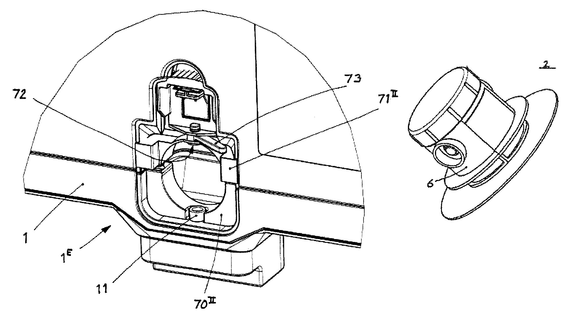
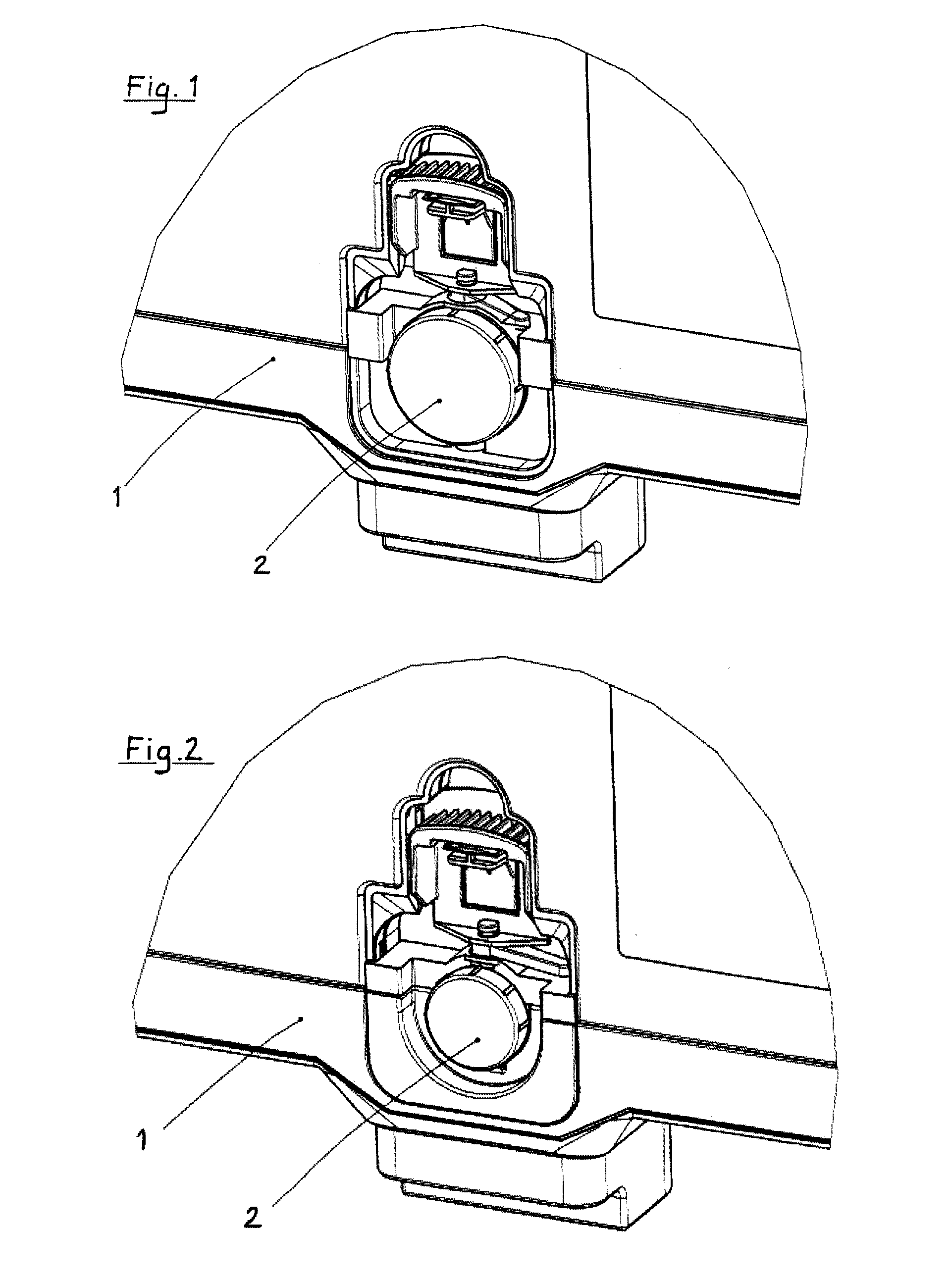
[0026]FIG. 1 show, in perspective view, part of a collapsible container 1. FIG. 1 show a valve assembly 2 in a valve opening 1E according to the invention.
second embodiment
[0027]FIG. 2 show, in perspective view, part of a collapsible container 1. FIG. 2 show a valve assembly 2 in a valve opening 1E according to the invention.
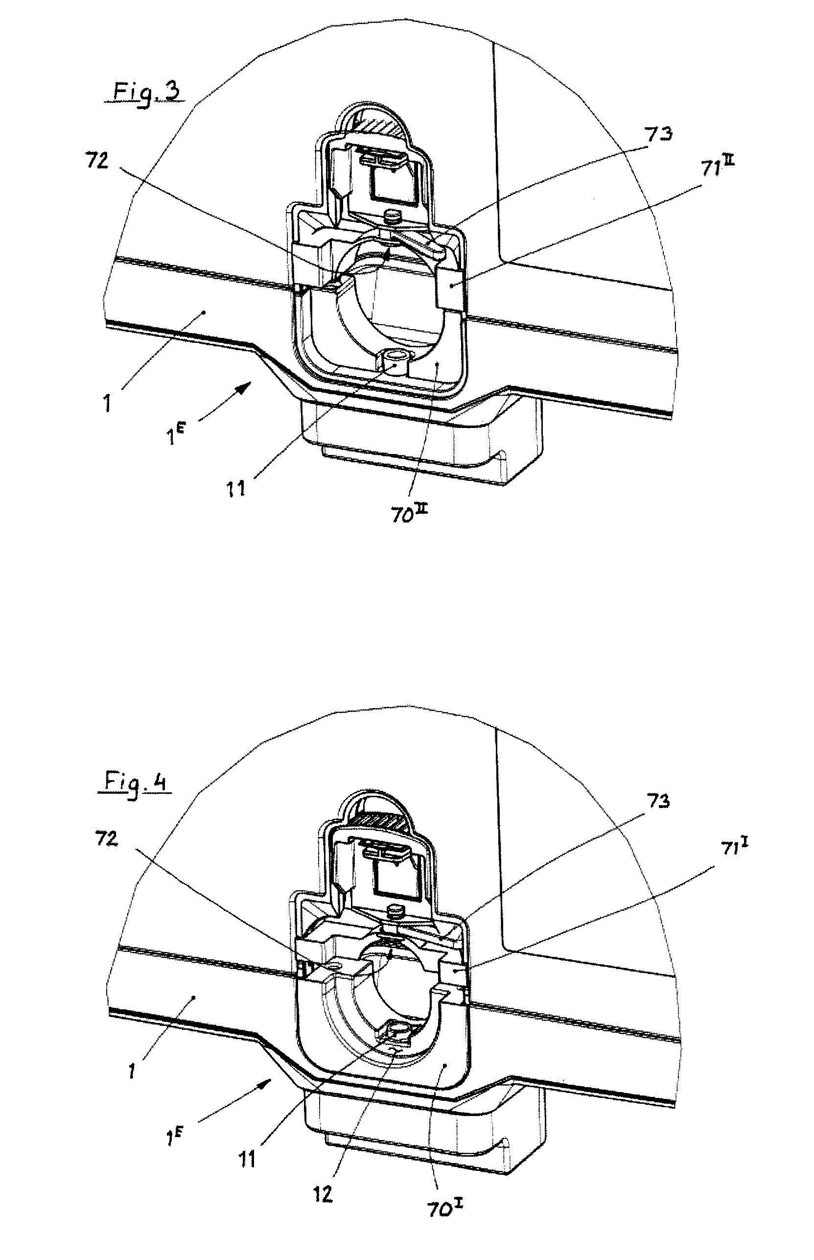
[0028]FIG. 3 show, in perspective view, the embodiment of FIG. 1 before insertion of liner and valve according to the invention.
[0029]FIG. 4 show, in perspective view, the embodiment of FIG. 2 before insertion of liner and valve according to the invention.
[0030]FIG. 5a show, in perspective view as seen from below, an embodiment of a valve assembly 3 according to the invention.
[0031]FIG. 5b show, in perspective view as seen from above, an embodiment of a valve assembly 3 according to the invention.
[0032]FIG. 5c show, in perspective view and in exploded view, an embodiment of a valve assembly 3 according to the invention.
[0033]FIG. 6 show, in perspective view, a valve size adapter 70I from FIG. 4.
[0034]FIG. 7 show, in perspective view, a matching upper member 71I from FIG. 4.
[0035]FIG. 8 show, in perspective and exploded view an alt...
PUM
Abstract
A valve assembly (2) intended for use together with a pallet container (1) and a liner. The valve assembly (2) comprises a support member (6). The support member (6) is provided with a guiding hole (63) intended to interact with a lower valve guide member (11).
Description
CROSS REFERENCE TO RELATED APPLICATIONS[0001]This application is a 35 U.S.C. §371 application of International Application PCT / SE2012 / 000123, filed Aug. 24, 2012, which claims priority of Swedish Patent Application No. 1100626-9, filed Aug. 29, 2011, the entire disclosures of which are herein incorporated by reference.BACKGROUND OF THE INVENTION[0002]1. Field of the Invention[0003]The present invention relates to a novel and improved valve assembly for hulk containers with liner and a container thereto.[0004]2. Description of Related Prior Art[0005]Products made of thermoplastic materials can be manufactured by a number of different manufacturing procedures. The most commonly used methods are however, injection moulding, vacuum forming, blow moulding and press moulding.[0006]Valves of butterfly and of ball type have been known for some time and they can be manufactured from thermoplastic material. Here injection moulding and press moulding are the most suited manufacturing methods i...
Claims
Application Information
Patent Timeline
Application Date:The date an application was filed.
Publication Date:The date a patent or application was officially published.
First Publication Date:The earliest publication date of a patent with the same application number.
Issue Date:Publication date of the patent grant document.
PCT Entry Date:The Entry date of PCT National Phase.
Estimated Expiry Date:The statutory expiry date of a patent right according to the Patent Law, and it is the longest term of protection that the patent right can achieve without the termination of the patent right due to other reasons(Term extension factor has been taken into account ).
Invalid Date:Actual expiry date is based on effective date or publication date of legal transaction data of invalid patent.
