
Shunt pulsation trap for cyclic positive displacement (PD) compressors

a compressor and pulsation trap technology, applied in the direction of pump components, positive displacement liquid engines, liquid fuel engine components, etc., can solve the problems of severe vibration and noise, damage to pipe lines and equipment, and all fixed pressure ratio compressors suffer from under-compression, etc., to achieve high reliability, simple structure, and compact size

Active Publication Date: 2015-09-22
HI BAR BLOWERS
View PDF24 Cites 8 Cited by
  • Summary
  • Abstract
  • Description
  • Claims
  • Application Information

AI Technical Summary

Benefits of technology

[0022]It is a further object of the present invention to provide a positive displacement compressor with a shunt pulsation trap in parallel with the compressor cavity that it is as efficient as a variable internal volume ratio design but with a much simpler structure and high reliability.
[0023]It is a further object of the present invention to provide a positive displacement compressor with a shunt pulsation trap in parallel with the compressor cavity that it is compact in size by eliminating the serially connected dampener at discharge.
[0024]It is a further object of the present invention to provide a positive displacement compressor with a shunt pulsation trap in parallel with the compressor cavity that is capable of achieving pulsation attenuation in a wide range of pressure ratios.
[0025]It is a further object of the present invention to provide a positive displacement compressor with a shunt pulsation trap in parallel with the compressor cavity that is capable of achieving higher pulsation attenuation in a wide range of speeds and cavity passing frequency.
[0026]It is a further object of the present invention to provide a positive displacement compressor with a shunt pulsation trap in parallel with the compressor cavity that is capable of achieving the same level of adiabatic efficiency in a wide range of pressure and speed without using a variable geometry.

Problems solved by technology

All fixed pressure ratio compressors suffer from under-compression due to varying system pressures.
They travel throughout the downstream piping system and if left uncontrolled, could potentially damage pipe lines and equipments, and excite severe vibrations and noises.
It is fairly effective in pulsation control with a reduction of 20-40 dB, but it itself is large in size which creates other problems like inducing more noises due to additional vibrating surfaces, or sometimes induces dampener structure fatigue failures that could result in catastrophic damages to downstream components and equipments.
At the same time, discharge dampeners used today create high pressure losses that contribute to poor compressor overall efficiency.
Moreover, at the off-design conditions, say either an under-compression or an over-compression, compressor efficiency suffers more.
These systems typically are very complicated structurally with high cost and low reliability.
For this reason, PD compressors are often cited unfavorably with high pulsations, high NVH and low off-design efficiency when compared with dynamic types like the centrifugal compressor.
It is this large pressure difference and potentially huge force that could directly damage system and components on its travelling path, in addition to exciting vibrations and noises.

Method used


Image

  • Shunt pulsation trap for cyclic positive displacement (PD) compressors
  • Shunt pulsation trap for cyclic positive displacement (PD) compressors
  • Shunt pulsation trap for cyclic positive displacement (PD) compressors

Examples


Embodiment Construction

)

[0039]Although specific embodiments of the present invention will now be described with reference to the drawings, it should be understood that such embodiments are examples only and merely illustrative of but a small number of the many possible specific embodiments which can represent applications of the principles of the present invention. Various changes and modifications obvious to one skilled in the art to which the present invention pertains are deemed to be within the spirit, scope and contemplation of the present invention as further defined in the appended claims.

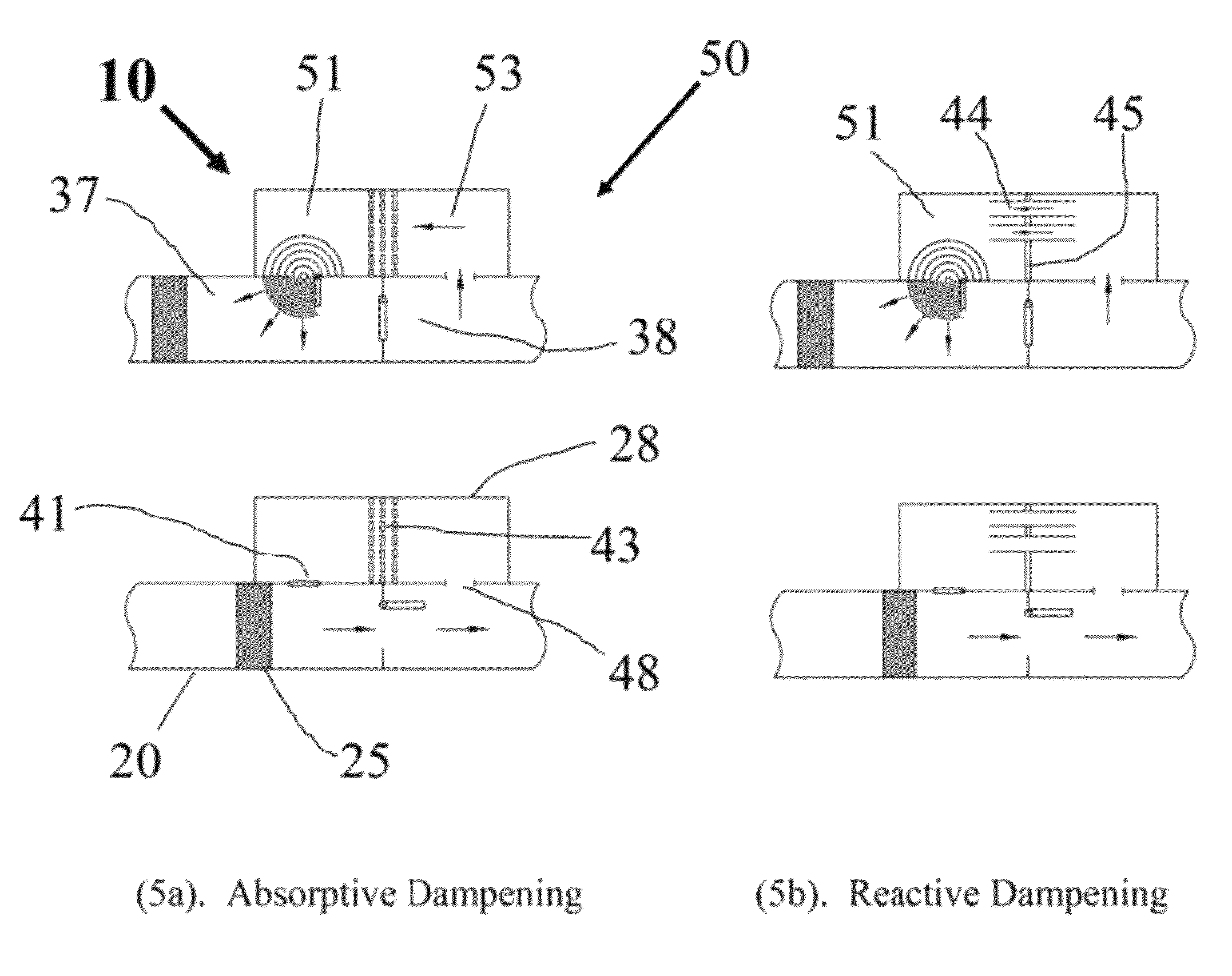
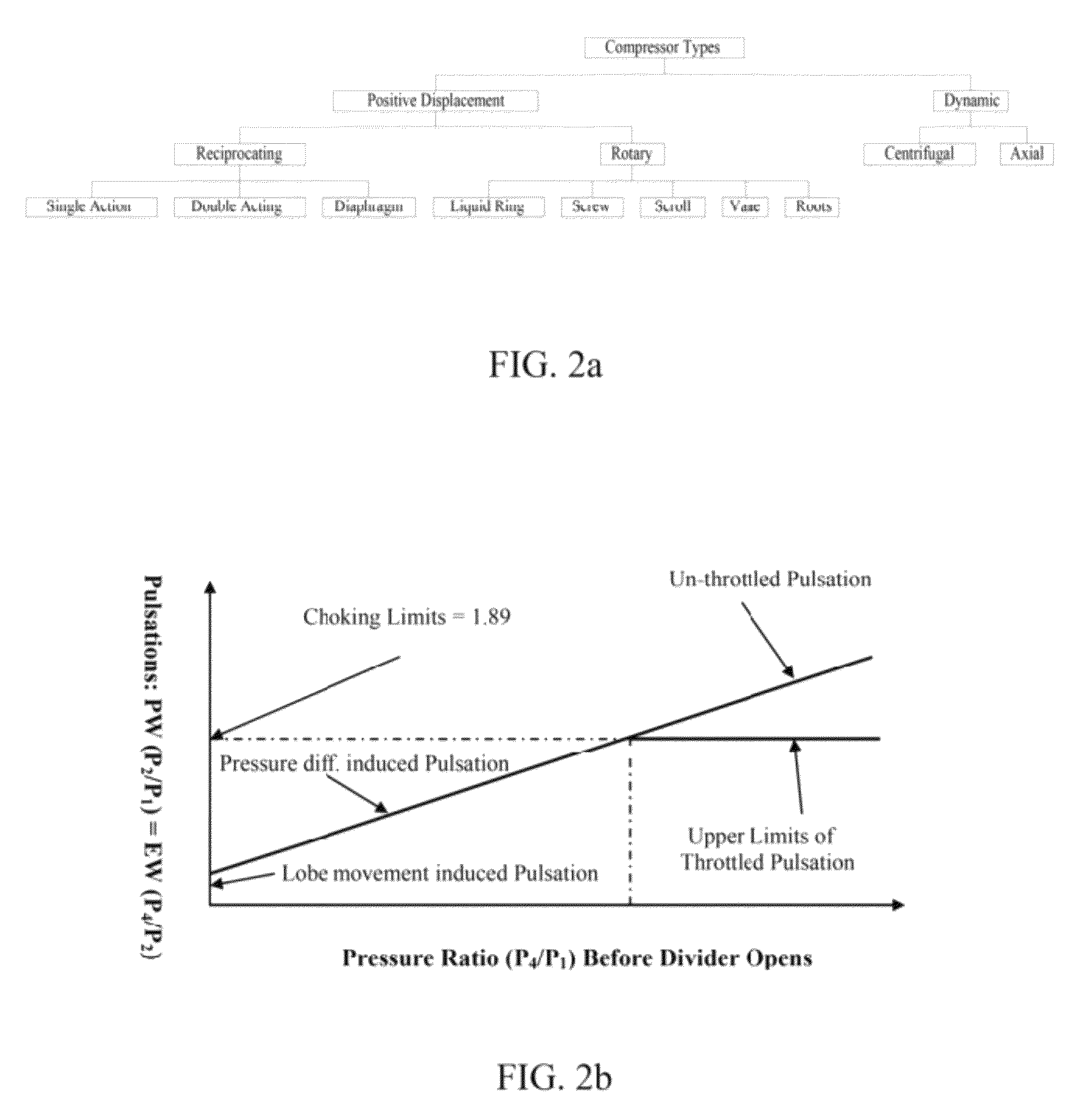
[0040]It should also be pointed out that though most drawing illustrations and description are devoted to a piston type gas compressor for controlling gas pulsations from under-compression mode in the present invention, the principle can be applied to other types of positive displacement compressors no matter it is a reciprocating or rotary as classified in FIG. 2a, because they all have the same pulsation control...


PUM


Abstract

A shunt pulsation trap for a cyclic positive displacement (PD) compressor reduces gas pulsation and NVH, and improves off-design efficiency, without using a traditional serial pulsation dampener and a variable geometry. A shunt pulsation trap for a cyclic PD compressor is configured to trap and attenuate gas pulsations before discharge and includes a housing having a flow suction port, a flow discharge port, a compressor cavity, and a pulsation trap chamber adjacent to the PD compressor cavity. The pulsation trap chamber includes at least one pulsation dampening device, at least one injection port (trap inlet) branching off from the PD compressor cavity into the pulsation trap chamber and a feedback region (trap outlet) communicating with the PD compressor outlet. The associated methods of reducing pulsations are included as another aspect of the invention.

Description

CLAIM OF PRIORITY[0001]This application claims priority to Provisional U.S. patent application entitled A SHUNT PULSATION TRAP FOR CYCLIC POSITIVE DISPLACEMENT (PD) COMPRESSORS, filed Mar. 14, 2011, having application No. 61 / 452,160, the disclosure of which is hereby incorporated by reference in its entirety.BACKGROUND OF THE INVENTION[0002]1. Field of the Invention[0003]The present invention relates generally to the field of positive displacement (PD) type blowers, compressors, and more specifically relates to a shunt pulsation trap for reducing gas pulsations and vibration, noise and harshness (NVH) and improving compressor off-design efficiency without using a traditional serial pulsation dampener or a sliding valve.[0004]2. Description of the Prior Art[0005]PD compressors are capable of generating high pressures for a wide range of flows and are widely used in various applications, for examples, as in pipeline transport of purified natural gas from the production site to consume...

Claims


Application Information

Patent Timeline
Patent Type & Authority Patents(United States)
IPC IPC(8): F04C29/06F04B11/00F04B39/00F04C29/00
CPCF04C29/061F04B11/00F04B11/0033F04B39/0027F04B39/0088F04C29/0035F04C29/065
Inventor HUANG, PAUL XIUBAOYONKERS, SEAN WILIAM
Owner HI BAR BLOWERS
Learn More