Active structures for heat exchanger

a technology of active structures and heat exchangers, applied in the field of thermal energy transfer, can solve the problems of increasing the transfer of thermal energy by unsteady flow

Active Publication Date: 2015-09-22
HAMILTON SUNDSTRAND CORP
View PDF49 Cites 4 Cited by
  • Summary
  • Abstract
  • Description
  • Claims
  • Application Information

AI Technical Summary

Benefits of technology

[0004]According to another aspect of the invention, a heat exchanger includes a plurality of channels and one or more a frame assemblies. The frame assembly includes a frame and one or more active flow disruption members affixed to the frame and disposed at an entrance to the plurality of channels. The one or more active flow disruption members are configured to induce unsteadiness in a flow through the plurality of channels to increase transfer of thermal energy therein.
[0005]According to yet another aspect of the invention, a method for transferring thermal energy from a heat exchanger includes locating one or more active flow disruption members at an entrance to a plurality of channels of the heat exchanger. A flow is directed across the one or more active flow disruption members into the plurality of channels and an unsteadiness is produced in the flow via the one or more active flow disruption members. The unsteadiness in the flow increases the transfer of thermal energy between the heat exchanger and the flow.

Problems solved by technology

The unsteadiness in the flow increases the transfer of thermal energy between the heat exchanger and the flow.

Method used


Image

  • Active structures for heat exchanger
  • Active structures for heat exchanger
  • Active structures for heat exchanger

Examples


Embodiment Construction

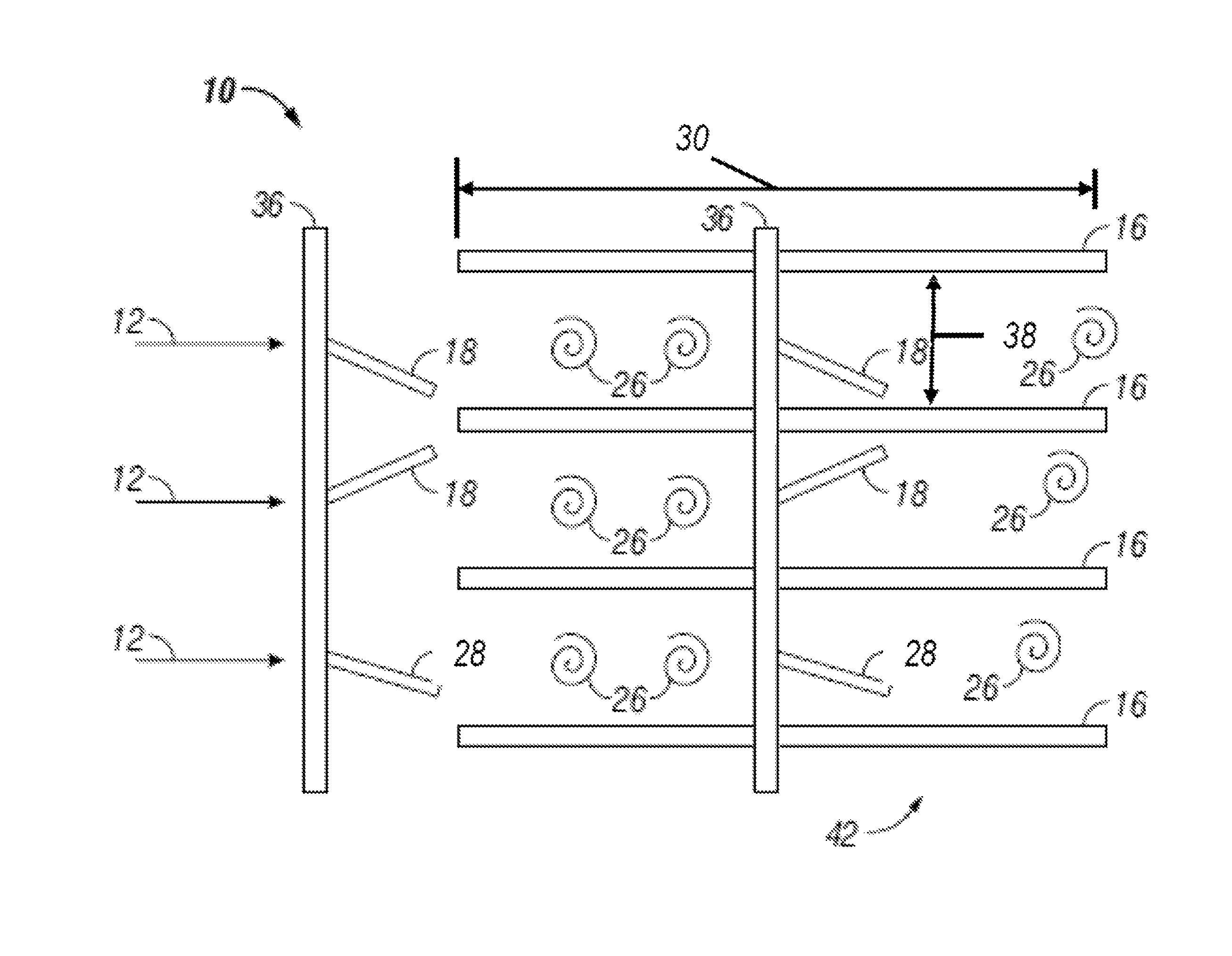
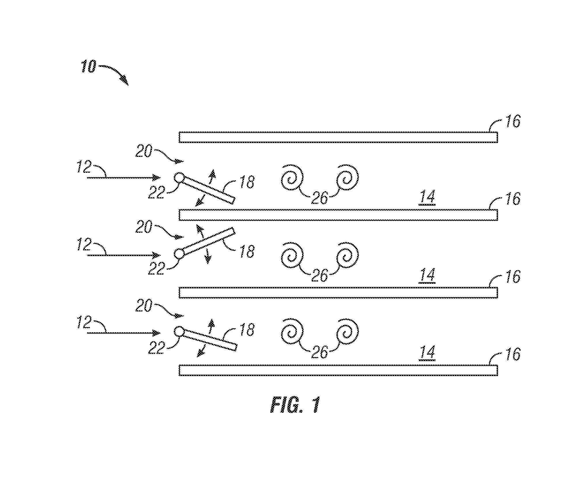
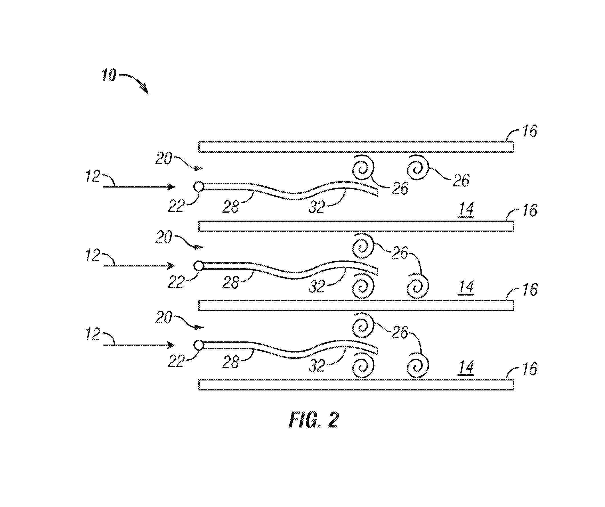
[0015]Shown in FIG. 1 is a schematic of an embodiment of a heat exchanger 10. A flow 12, of for example, air flows through a plurality of channels 14, the sides of which are defined by a plurality of heat transfer fins 16. As the flow 12 travels through the channels 14, thermal energy is transferred from the heat transfer fins 16 to the flow 12. The flow 12 may be induced by a source such as a blower (not shown).

[0016]An active flow disruption member, for example, an active vibratory member such as a rigid tab 18 is located at the entrance 20 of each channel 14. Each tab 18 is secured in the entrance 20 via, for example a wire 22 or torsional spring. Further, the tab 18 is disposed at an angle to the incoming flow 12 such that the tab 18 is deflected about an axis defined by the wire 22 by the flow 12. The wire 22 holding the tab 18 is set with a tension such that a resonant frequency of the tab 18 vibration held by the wire 22 is at or near a vortex shedding frequency of the tab 18...


PUM


Abstract

A heat exchanger includes a plurality of channels and one or more active flow disruption members disposed at an entrance to the plurality of channels. The active flow disruption members are configured to induce unsteadiness in a flow through the plurality of channels to increase thermal energy transfer in the plurality of channels. A method for transferring thermal energy from a heat exchanger includes locating one or more active flow disruption members at an entrance to a plurality of channels of the heat exchanger. A flow is directed across the one or more active flow disruption members into the plurality of channels and an unsteadiness is produced in the flow via the one or more active flow disruption members. The unsteadiness in the flow increases the transfer of thermal energy between the heat exchanger and the flow.

Description

BACKGROUND OF THE INVENTION[0001]The subject matter disclosed herein relates to thermal energy transfer. More specifically, the subject disclosure relates to active structures for enhancement to thermal energy transfer in, for example, a heat exchanger.[0002]A heat exchanger transfers thermal energy to a flow through channels in the heat exchanger from a structure surrounding the channels. The thermal energy in the structure is then removed from the system via the cooling flow. The art would well receive means of increasing the heat transfer in the heat exchanger channels.BRIEF DESCRIPTION OF THE INVENTION[0003]According to one aspect of the invention, a heat exchanger includes a plurality of channels and one or more active flow disruption members disposed at an entrance to the plurality of channels. The active flow disruption members are configured to induce unsteadiness in a flow through the plurality of channels to increase thermal energy transfer in the plurality of channels.[00...

Claims


Application Information

Patent Timeline
Patent Type & Authority Patents(United States)
IPC IPC(8): F28F13/12F28F13/06H05K7/20
CPCF28F13/06F28F13/12F28F13/125
Inventor KASLUSKY, SCOTT F.ST. ROCK, BRIANLEE, JAESEONJIANG, YIRONG
Owner HAMILTON SUNDSTRAND CORP
Why Eureka
Try Eureka