
Fuel system for injection of a fuel mixture in a combustion engine

a fuel mixture and combustion engine technology, which is applied in the direction of liquid fuel feeders, machines/engines, mechanical apparatuses, etc., can solve the problems of difficult mixing of certain fuels and cold starts, and achieve the effect of good mixing of the two fuels and a relatively simple fuel system

Inactive Publication Date: 2015-09-29
SCANIA CV AB
View PDF19 Cites 0 Cited by
  • Summary
  • Abstract
  • Description
  • Claims
  • Application Information

AI Technical Summary

Benefits of technology

[0006]The object of the present invention is to propose a fuel system with relatively few components which makes it possible to inject a fuel mixture at high pressure in a combustion engine.
[0007]The above object is achieved with the fuel system of the kind mentioned in the introduction which is characterised by the features of the invention. The first fuel and the second fuel are received in a suitable space in the inlet circuit which leads fuel to the engine. A mixing device is provided downstream of that space in the flow direction of the fuel. The mixing device mixes with advantage the two fuels to a substantially uniform fuel mixture. However, it is difficult to mix certain fuels, e.g. ethanol with hydrocarbon fuels. In such cases, the mixing device has to be so effective that an emulsion is created. To create an emulsion, the mixing device has to be capable of breaking up at least one fuel to such small drops that they can float freely around in the other fuel. The present invention therefore uses an inlet circuit with a feed pump, a high-pressure pump, an accumulator tank and at least one injection unit. When such components are used, the fuel mixture can be pressurised and be injected at a high pressure in the engine. Using a suitable space to receive the two fuels and a suitable mixing device makes it possible for the fuel system to be fairly simple and not much more complicated than a fuel system for injection of one fuel.
[0008]According to an embodiment of the present invention, said space is situated at a location upstream of the feed pump in the inlet circuit with respect to the intended direction of fuel flow in the inlet circuit. Such a location of the space makes it possible to use the feed pump to convey both the first fuel and the second fuel to the space. This means that only one feed pump need be used to transfer the two fuels. With advantage, the feed pump is used as a mixing device. A feed pump applies more or less effective mixing movements to two fuels which it transfers in the inlet circuit. A suitable feed pump makes it possible to achieve a good mixture of the two fuels passing through the feed pump. Using an existing feed pump to mix the two fuels therefore makes it unnecessary to provide separate mixing means in the inlet circuit. The feed pump is with advantage a gear pump. Gear pumps usually comprise two gearwheels which rotate in mutual engagement, making it possible to achieve very good mixing of the two fuels so that an emulsion is created.
[0009]According to another embodiment of the present invention, the first fuel source comprises a first fuel tank and a first fuel line which leads the first fuel from the first fuel tank to the space in the inlet circuit. The first fuel may be the main fuel and may therefore be the main constituent of the fuel mixture. The first fuel line may with advantage be connected to a space in the inlet circuit on the inlet side of the feed pump in the fuel flow direction. This makes it possible for the feed pump to draw the first fuel in the inlet circuit from the first fuel tank via the first fuel line. The first fuel line may comprise a control device by which the flow of the first fuel to the space can be regulated. Such a control device may comprise an automatically or manually operable valve by which it is possible to completely halt the supply of the first fuel. This control may arise in operating situations where it is appropriate to use only the second fuel for operation. Such operating situations may be cold starts. Another such operating situation may be when a vehicle is to be out of action for a time and it is desired to prevent the first fuel from remaining in the inlet circuit if for example the first fuel is corrosive. Alternatively, the control device may comprise a fixed or adjustable throttle valve by which a fixed or variable reduced flow of the first fuel to the space can be provided. The proportion of the first fuel in the fuel mixture can thus be maintained at a constant level or varied to suit different operating situations.

Problems solved by technology

However, it is difficult to mix certain fuels, e.g. ethanol with hydrocarbon fuels.
Using an existing feed pump to mix the two fuels therefore makes it unnecessary to provide separate mixing means in the inlet circuit.
Such operating situations may be cold starts.

Method used


Image

  • Fuel system for injection of a fuel mixture in a combustion engine
  • Fuel system for injection of a fuel mixture in a combustion engine

Examples


Embodiment Construction

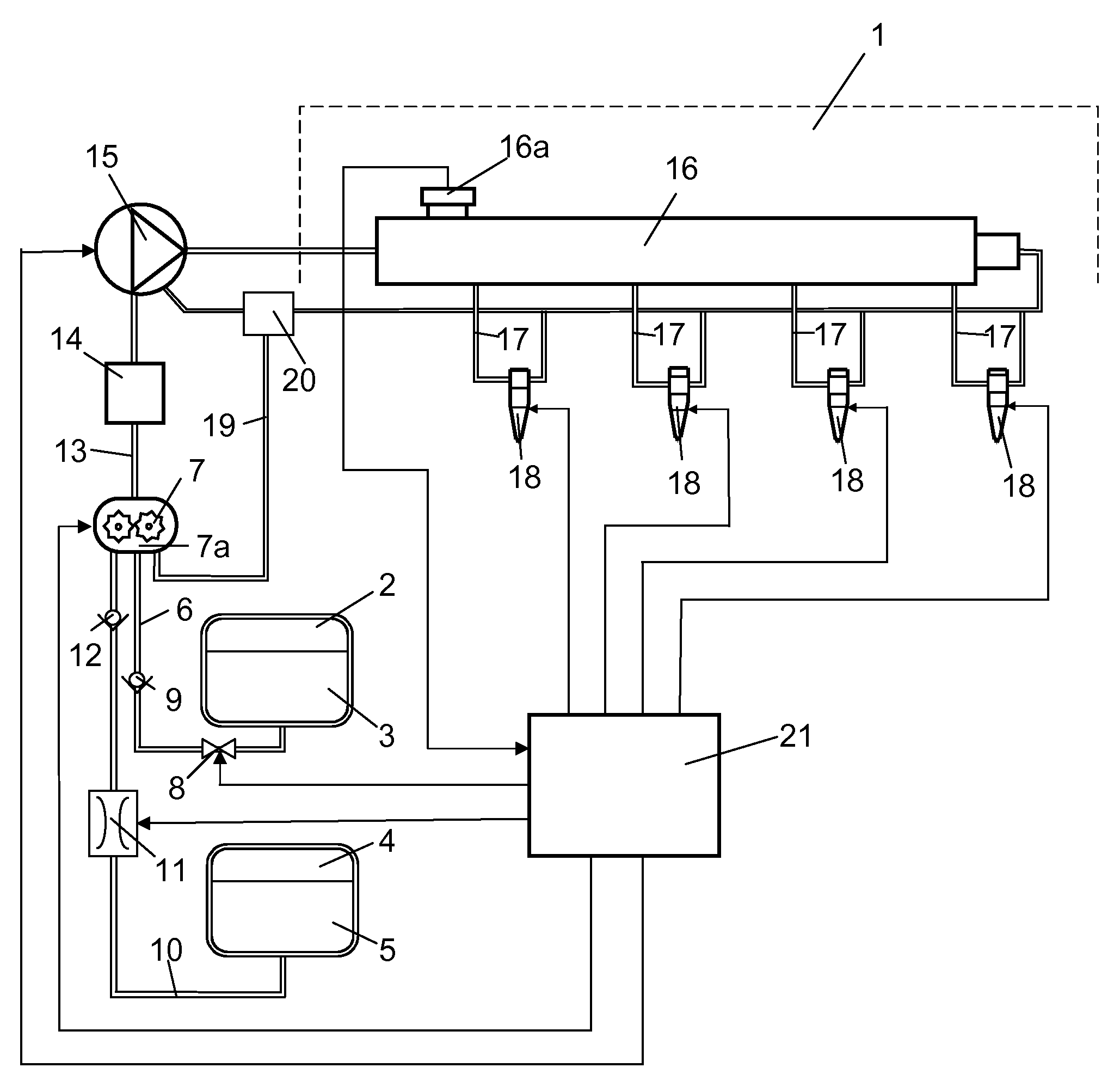
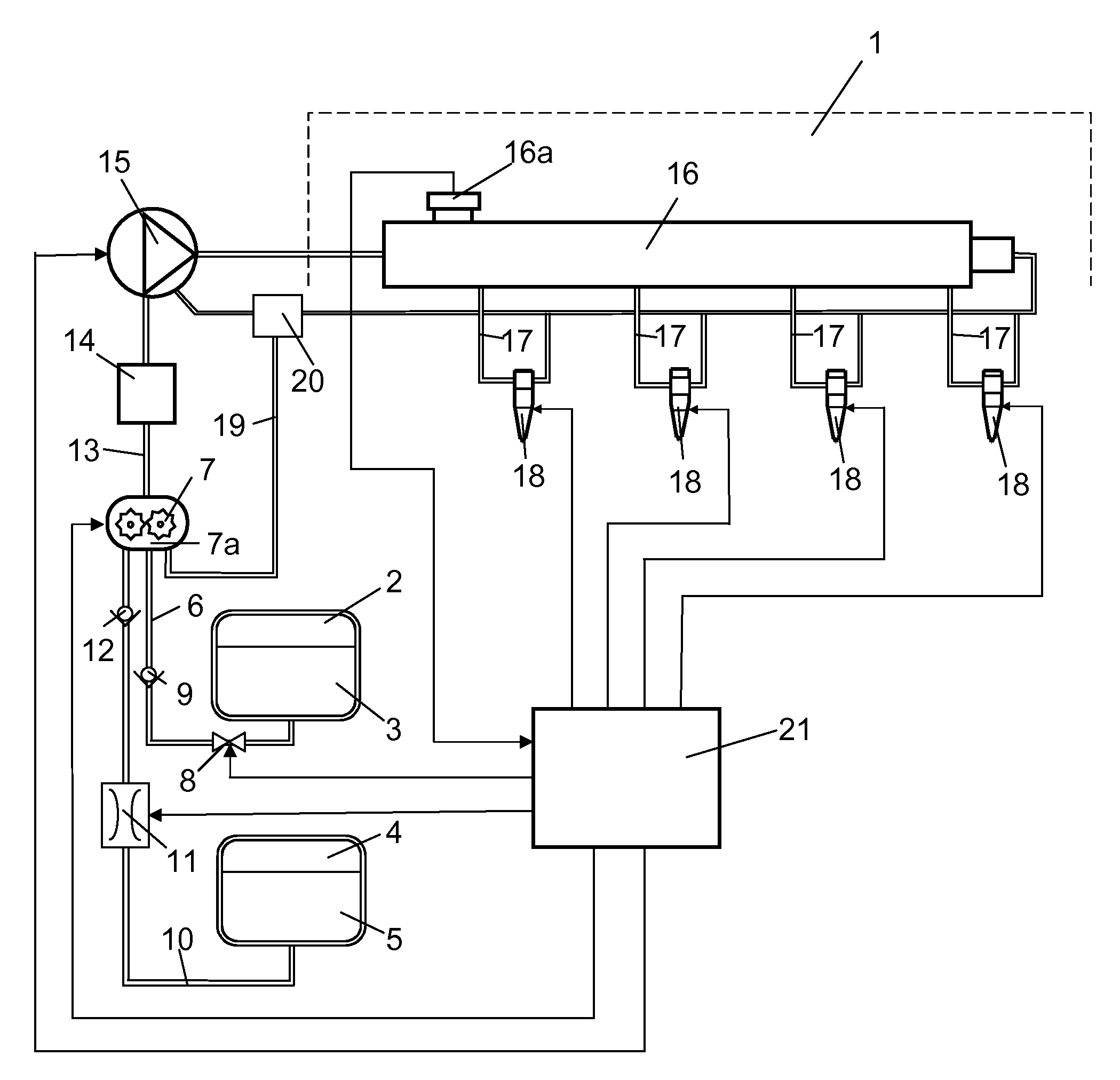
[0014]FIG. 1 depicts a fuel system which makes it possible to inject a fuel mixture at a high pressure in a combustion engine 1. The engine 1 is schematically indicated in the drawing. Injecting the fuel mixture at a high pressure reduces the discharge of emissions from the engine 1. The fuel system and the engine 1 may be fitted in a heavy vehicle. The fuel system comprises a first fuel tank 2 with a first fuel 3. The fuel system comprises a second fuel tank 4 with a second fuel 5. The first fuel 3 is in this case the main fuel and the second fuel 5 a supplementary fuel. The first fuel is in this case a relatively less readily ignitable fuel which may be ethanol. The second fuel is a more readily ignitable fuel which may be diesel fuel. A first fuel line 6 extends from the first fuel tank 2 to a space 7a on the inlet side of a feed pump which in this case is a gear pump 7. The first fuel line 6 comprises a valve 8 which can be placed in an open position and a closed position. The f...


PUM


Abstract

A fuel system for injection of a fuel mixture in a combustion engine includes an inlet circuit (13, 17) leading fuel to the engine (1). The inlet circuit (13) includes a feed pump (7), a high-pressure pump (15), an accumulator tank (16), and at least one injection unit (18) injecting fuel in a combustion space of the engine (1). The inlet circuit (13, 17) includes a space (7a) for receiving a first fuel (3) from a first fuel source (2, 6) and a second fuel (5) from a second fuel source (4, 10). A mixing device (7) mixes to the first fuel (3) and the second fuel (5) resulting in a substantially uniform fuel mixture which the injection unit (18) injects into the engine's combustion space.

Description

CROSS-REFERENCE TO RELATED APPLICATIONS[0001]The present application is a 35 U.S.C. §§371 national phase conversion of PCT / SE2011 / 050765, filed Jun. 17, 2011, which claims priority of Swedish Application No. 1050663-2, filed Jun. 22, 2010, the contents of which are incorporated by reference herein. The PCT International Application was published in the English language.BACKGROUND TO THE INVENTION AND PRIOR ART[0002]The present invention relates to a fuel system for injection of a fuel mixture in a combustion engine.[0003]A way of reducing the discharge of emissions from combustion engines is to inject the fuel at a very high pressure. A so-called “common rail” system is widely used to effect injection at a high pressure in the combustion spaces of a diesel engine. A common rail system comprises a high-pressure pump which pumps fuel at a very high pressure to an accumulator tank (common rail). The pressure in the accumulator tank during operation may be of the order of 350-1600 bar. ...

Claims


Application Information

Patent Timeline
Patent Type & Authority Patents(United States)
IPC IPC(8): F02M37/00F02B7/00F02M43/00F02D19/06F02M25/00F02M63/02F02D19/08
CPCF02M43/00F02D19/0655F02D19/0665F02D19/0684F02D19/081F02M37/0088F02M63/0225Y02T10/36Y02T10/30F02M37/0064F02M43/02
Inventor KYLSTROM, KIM
Owner SCANIA CV AB
Learn More