Load rating optimized bevel gear toothing

a technology of load rating and bevel gear, applied in the field of toothed gear, can solve problems such as damage to the tooth flank, and achieve the effect of improving the load rating and increasing the torqu

Active Publication Date: 2015-09-29
SCHOTTEL +1
View PDF17 Cites 4 Cited by
  • Summary
  • Abstract
  • Description
  • Claims
  • Application Information

AI Technical Summary

Benefits of technology

[0007]The object of this invention is to optimize a bevel gear of the type referenced above so as to improve its load rating and to enable increased torque to be transmitted by the bevel gear.

Problems solved by technology

Damage to tooth flanks occurs, for example, in response to excessively high contact pressures.

Method used


Image

  • Load rating optimized bevel gear toothing
  • Load rating optimized bevel gear toothing
  • Load rating optimized bevel gear toothing

Examples


Embodiment Construction

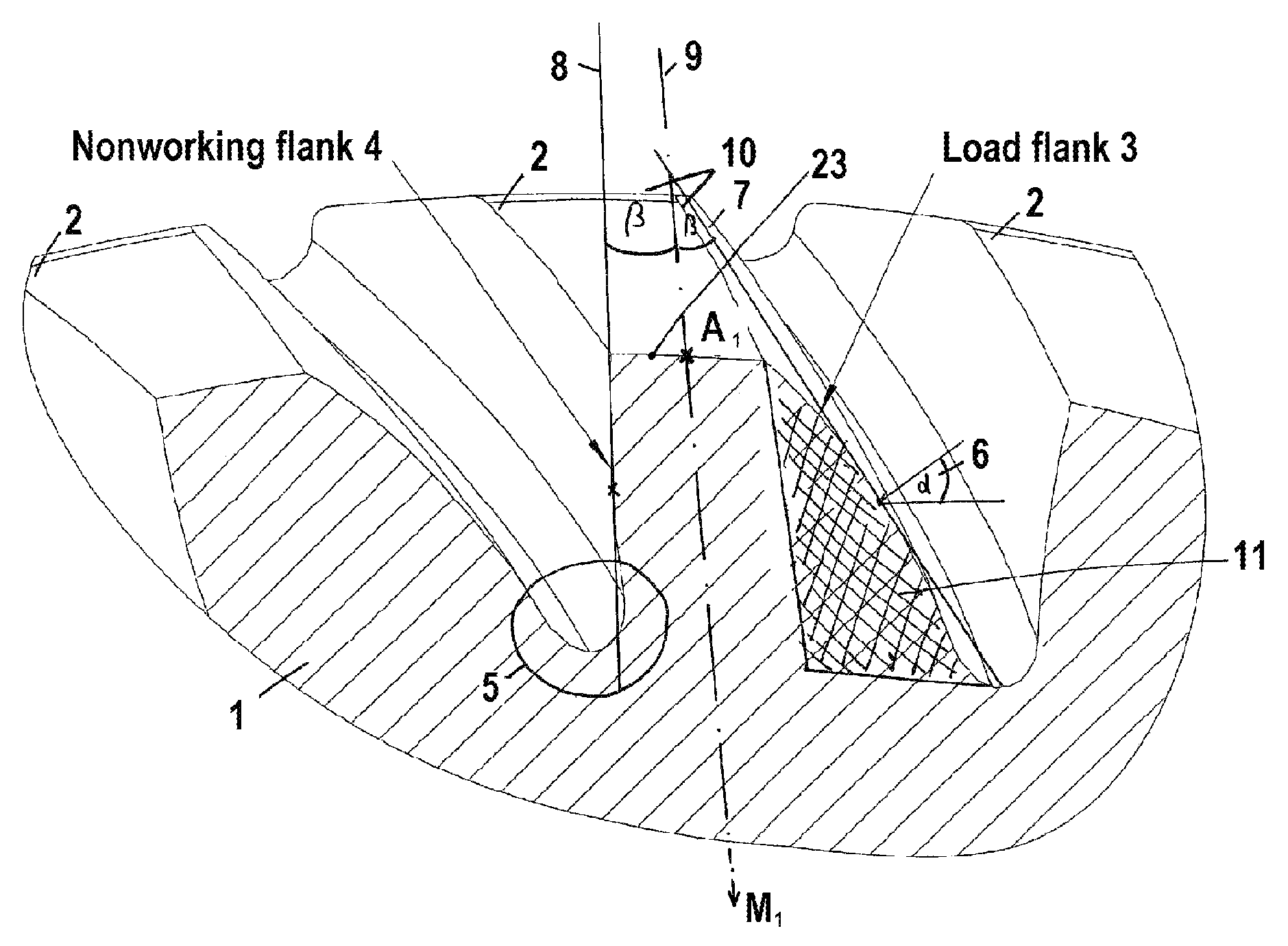
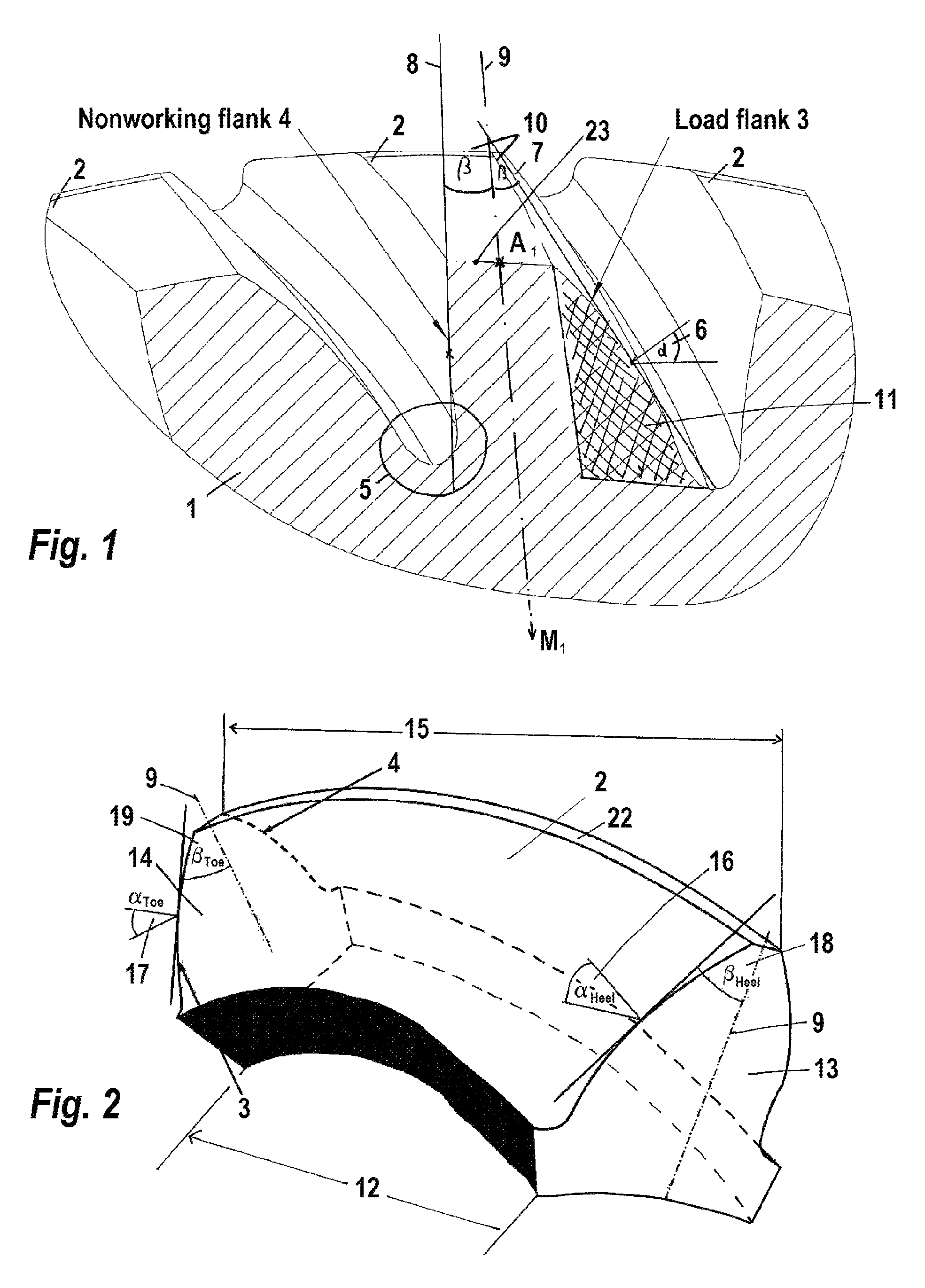
[0025]FIG. 1 shows a bevel gear 1 that has multiple teeth 2 distributed around its circumference, each of which has a load flank 3 and a nonworking flank 4. The load flank 3 and the nonworking flank 4 of two adjacent teeth 2 are connected by a tooth root region 5, also called the “bottom land.”

[0026]Since a preferred direction of rotation is intended for the transmission of torque, the load flanks 3 and the nonworking flanks 4 have different functions that are determined by a differing geometry.

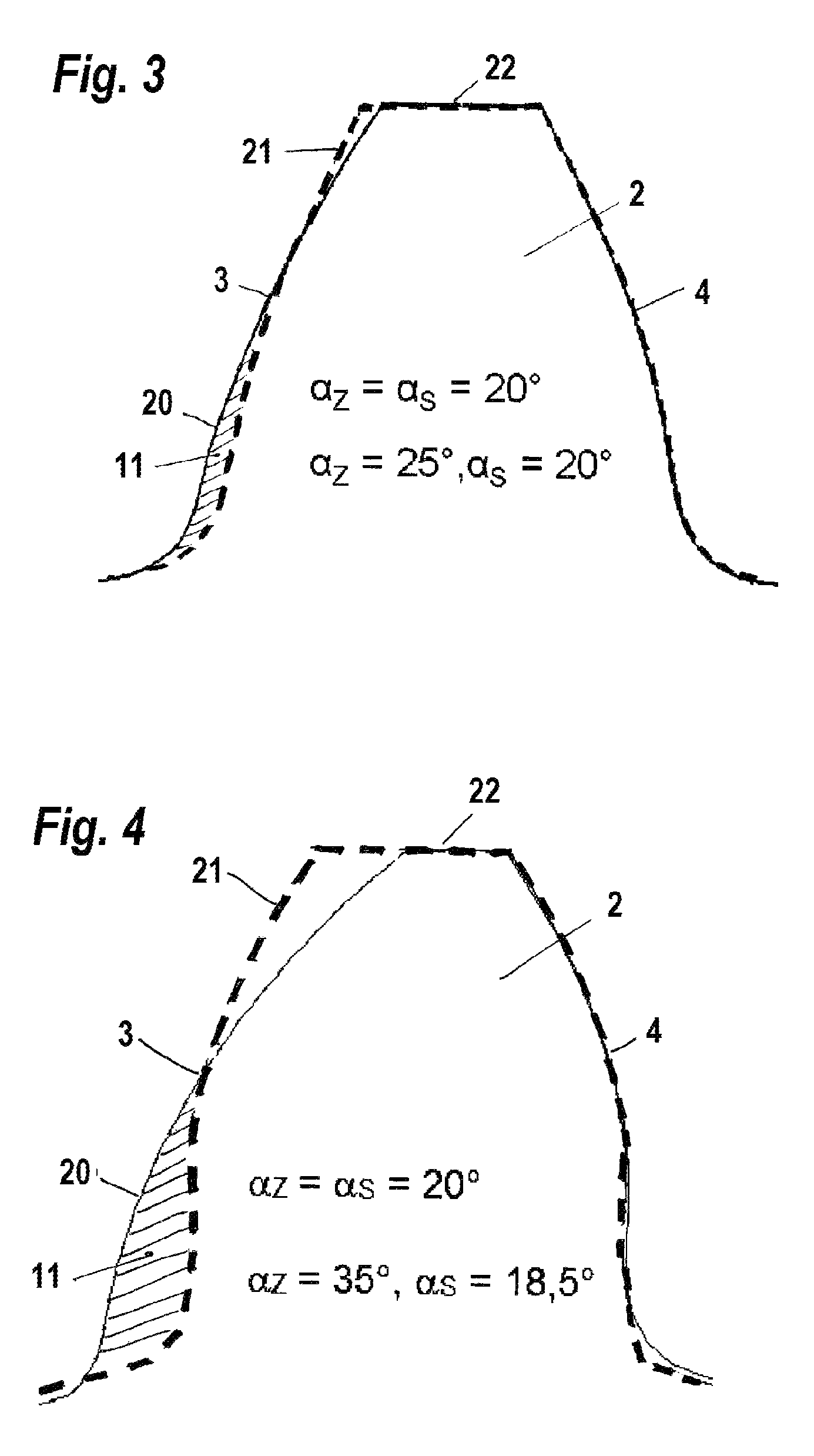
[0027]The load flank 3 serves for torque transmission during normal operation and is designed with a large pressure angle α6. Pressure angles α of the load flank 3 here measure 25° to 45°, preferably 30° to 40°. The nonworking flank 4 is designed with smaller pressure angles. Due to a flatter tangent 7 at any given point along the load flank 3, illustrated here on the pitch circle or rolling circle, relative to a corresponding tangent 8 of the nonworking flank 4, the tooth has an asymmetrical...


PUM

PropertyMeasurementUnit
pressure anglesaaaaaaaaaa

Abstract

The invention relates to a bevel gear wheel (1) of a bevel gear unit, each tooth (2) of which comprises a load flank (3) and a non-working flank (4), wherein the teeth (2) have a helical or spiral tooth trace, in particular a curved tooth longitudinal line, and the teeth (2), in particular the upper meshing region of the teeth, have an octoid tooth shape or a spherical involute tooth shape, and the teeth have an excess material quantity (11) on the load flanks (4) in order to reinforce the load flanks (4), in particular such that the axis (9) that runs through the tooth tip-bisecting point A1 of the tooth tip transverse line (23) and through the midpoint of the gear wheel exhibits asymmetry of the teeth (2). The invention further relates to a method for producing a bevel gear wheel (1) according to one of the preceding claims, in which the tooth geometry is produced by a four-axis or multi-axis method, in particular a five-axis method.

Description

CROSS REFERENCE TO RELATED APPLICATIONS[0001]This application is the U.S.-national stage of PCT application PCT / EP2011 / 002626 filed 27 May 2011, published 1 Dec. 2011 as WO2011 / 147582, and claiming the priority of German patent application 102010021771.9 itself filed 27 May 2010.FIELD OF THE INVENTION[0002]The invention relates to a toothed gear of a bevel gear unit whose teeth each have a load flank and a nonworking flank, and to a method of making it.BACKGROUND OF THE INVENTION[0003]The design of the tooth geometry of bevel gears is generally effected symmetrically relative to an axis of symmetry that runs through the gear center and radially through the tooth. This is justified on the basis that toothed gears are generally designed and produced to operate equally in both directions (forward and backward).[0004]Depending on the direction of operation, an individual tooth during the transmission of torque has a load flank that is engaged and transmits the torque to the load flank o...

Claims


Application Information

Patent Timeline
Patent Type & Authority Patents(United States)
IPC IPC(8): F16H55/08B23F9/02F16H1/00B23F9/00F16H55/17B23F9/08F16H55/10
CPCF16H55/17B23F9/00B23F9/02B23F9/08F16H1/003F16H55/08Y10T29/49467Y10T74/1987Y10T409/103975F16H1/00
Inventor POTTS, MICHAELSCHLECHT, BERTHOLDSENF, MICHAELSCHAEFER, STEFFENHUTSCHENREITER, BIRGIT
Owner SCHOTTEL
Why Eureka
Try Eureka