Track lighting system

Active Publication Date: 2015-10-06
AHEARN DAVID J
View PDF26 Cites 7 Cited by
  • Summary
  • Abstract
  • Description
  • Claims
  • Application Information

AI Technical Summary

Benefits of technology

[0018]The one or more directional task lighting assemblies is attached to a bottom portion of the housing assembly to provide lighting to work surface areas used by a practitioner in the operatory environment. The one or more directional task lighting assemblies includes one or more directional LEDs or other light producing members or elements to provide light to specific surface areas in the operatory environment. The one or more directional task lighting assemblies, in one embodiment, includes three directional LEDS to provide light to surrounding work surface areas in the operatory environment. In one embodiment, the task lighting assembly is located proximal to the electronic display. In operation, the track lighting system and the electronic display is more easily controlled by the practitioner in the operatory environment since all of the lighting options and electronic display are convenient to the practitioner in a single track lighting system which is important, especially during an operation.
[0020]It is a further object of the present invention is to improve the practitioner's ability to manipulate his lighting options and electronic display using a single track lighting system.
[0021]It is also an object of the present invention to provide enhanced lighting options in the operatory environment to improve the performance and efficiency of the practitioner by allowing the intraoral lamp assembly to move independent of the electronic display.
[0022]Another object of the present invention is to minimize the usage of space in the operatory environment by using a single track lighting system.
[0023]Furthermore, another object of the present is to provide electronic display respectively above a patient's head at a fixed position to prevent the practitioner from needlessly bumping into or constantly adjusting the electronic display.

Problems solved by technology

However, these lighting products are only single solution products, designed solely for exam lighting of an oral cavity of a patient.

Method used


Image

  • Track lighting system
  • Track lighting system
  • Track lighting system

Examples


Embodiment Construction

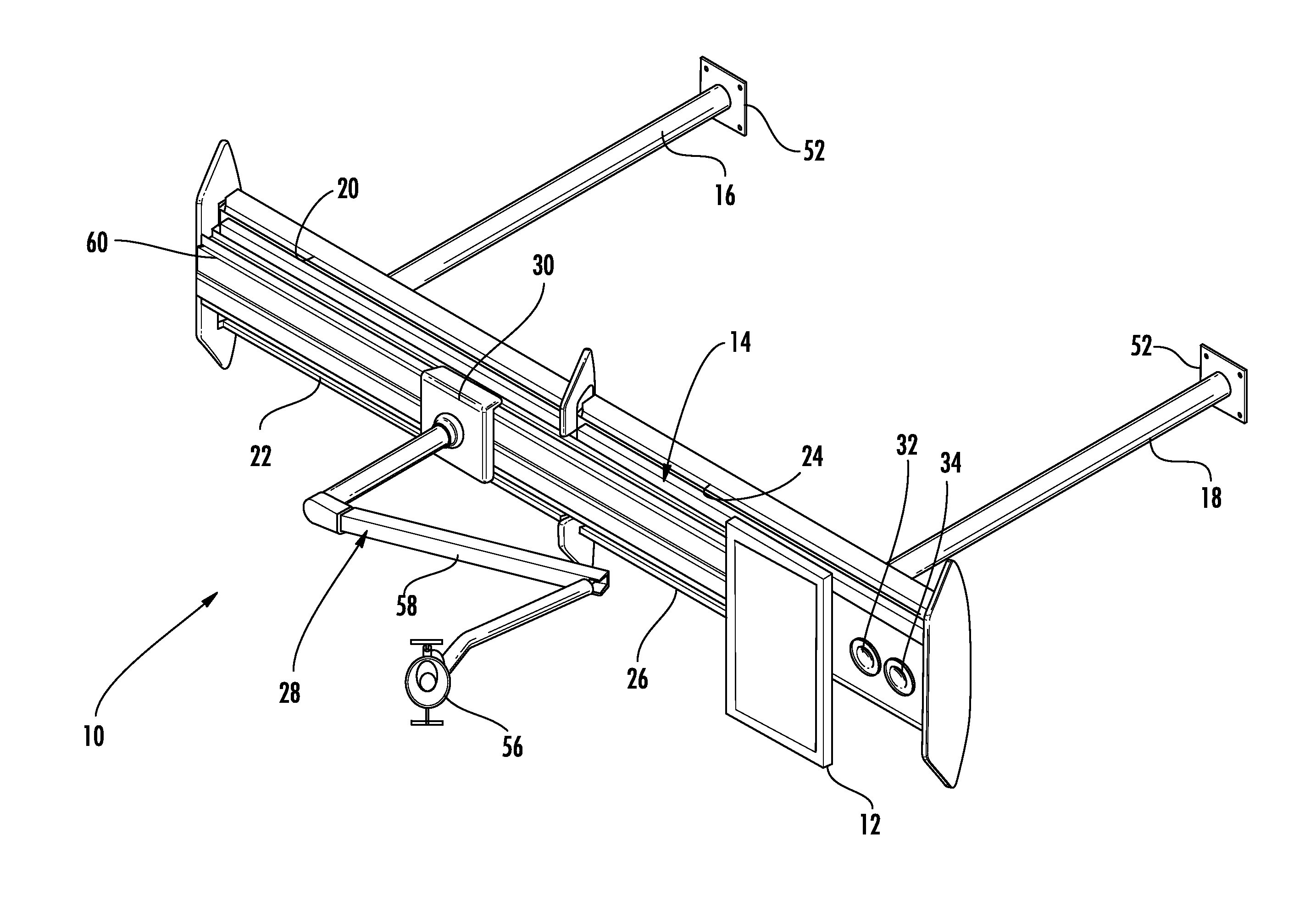
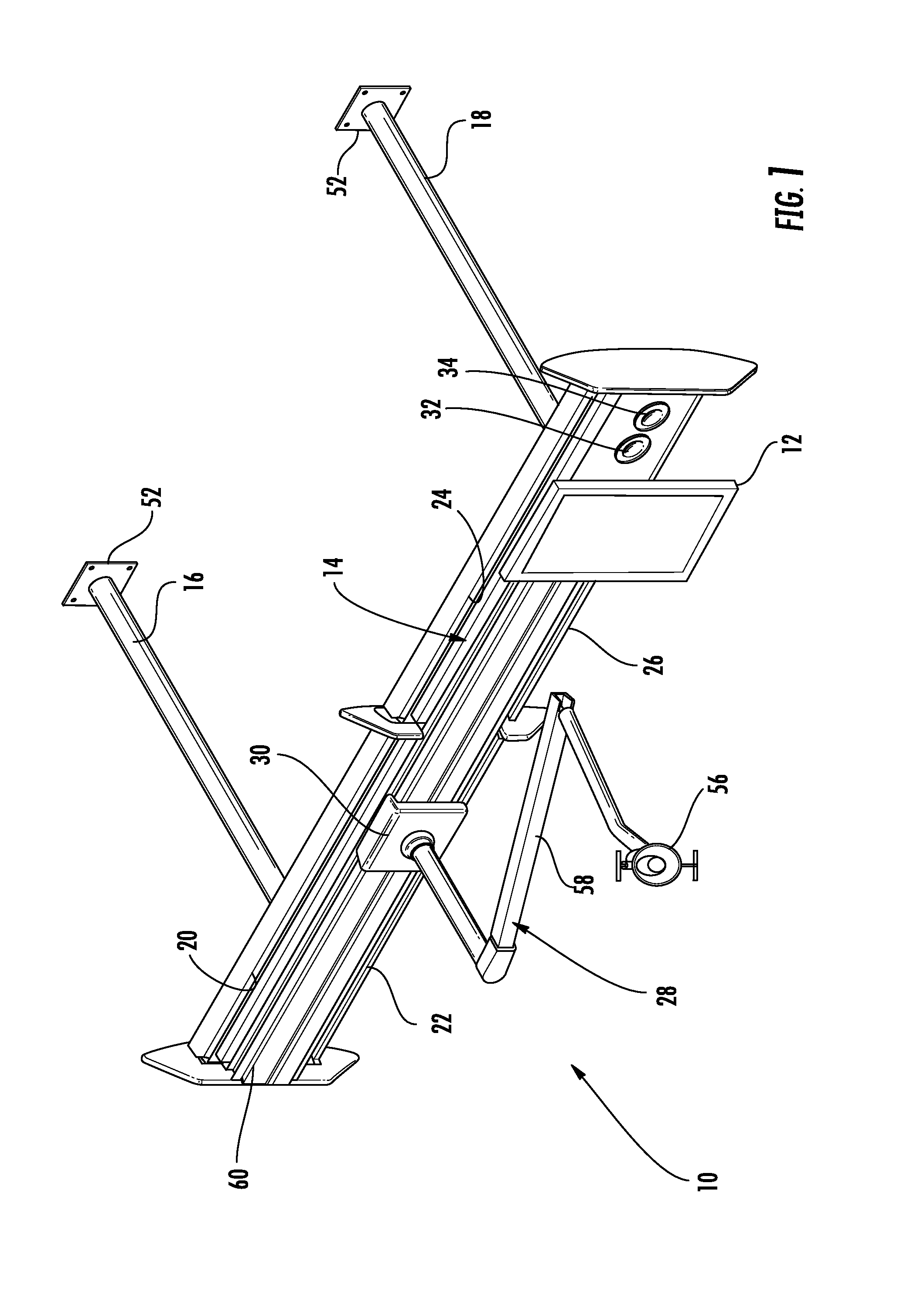
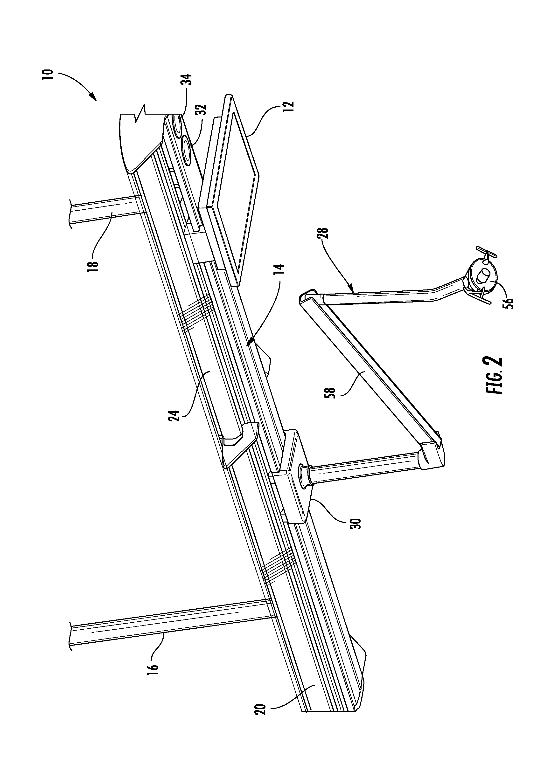
[0038]In FIGS. 1-12, the pendant mounted track lighting system 10 with electronic display 12 for use in an operatory environment is shown. In particular, the invention is directed towards a pendant mounted track lighting system 10 that incorporates and integrates intraoral illumination for illuminating a patient's oral cavity, general room or ambient lighting in the operatory environment for patients and practitioners, directional task lighting for work surface areas, and electronic display, such as a television or computer monitor, for patient stimulation during treatment. The invention will provide the lighting options (intraoral illumination, ambient lighting, directional task lighting) and the electronic display in a single track lighting system to improve overall delivery of operatory services in the operatory environment and minimize the usage of space in the operatory environment which is at a premium.

[0039]It should be understood that this invention is well suited and prefer...


PUM


Abstract

A pendant mounted track lighting system includes an electronic display for use in an operatory environment. In particular, the invention is directed towards a pendant mounted track lighting system that incorporates and integrates intraoral illumination for illuminating a patient's mouth area, general room or ambient lighting in the operatory environment for patients and practitioners, directional task lighting for work surface areas, and electronic display for patient stimulation. The track lighting system includes a housing assembly attached to one or more elongated members for attachment within the operatory environment, one or more ambient lighting assemblies, an intraoral light assembly having a carriage mechanism, an electronic display, and one or more directional task lighting assemblies in a single track lighting system.

Description

CROSS REFERENCE TO RELATED APPLICATION[0001]This application is related to and claims priority from earlier filed provisional patent application Ser. No. 61 / 418,427, filed Dec. 1, 2010 and incorporated herein by reference.BACKGROUND OF THE INVENTION[0002]The invention generally relates to track mounted lighting. In particular, the invention is directed towards a pendant mounted track lighting system that incorporates and integrates intraoral illumination for illuminating a patient's oral cavity, general room or ambient lighting in the operatory environment for patients and practitioners, directional task lighting for work surface areas, and electronic display for patient stimulation all in a single track lighting system.[0003]It is often necessary to move a light source such as an electric light within a room or other space to provide lighting where it is most needed. One response to this desire for portability is found in track lighting, which is found in many residential and comme...

Claims


Application Information

Patent Timeline
Patent Type & Authority Patents(United States)
IPC IPC(8): A61B1/06A61C19/00F21S8/06F21V21/28F21W131/202
CPCA61C19/00F21S8/066F21V21/28F21W2131/202A61B1/00128A61B1/247
Inventor AHEAM, DAVID JCAREY, EDWARD
Owner AHEARN DAVID J
Why Eureka
Try Eureka