Retractable cable tray for vertical structures

a vertical structure and cable tray technology, applied in the direction of machine supports, other domestic objects, mechanical apparatus, etc., can solve the problems of difficulty and time-consuming tasks associated with the relocation of drilling rigs, the disconnection and storage of numerous electrical, pneumatic, etc., and the speed of disassembly and assembly is also critical

Active Publication Date: 2015-10-06
T & T ENG SERVICES
View PDF19 Cites 29 Cited by
  • Summary
  • Abstract
  • Description
  • Claims
  • Application Information

AI Technical Summary

Benefits of technology

[0012]An actuator is pivotally connected to the mast and the linkage assembly such that extension and retraction of the actuator results in deployment and retraction of the cable tray assembly.

Problems solved by technology

These locations are often remotely located and in rough terrain.
One of the difficult and time consuming tasks associated with relocating a drilling rig is the disconnection and storage of the numerous electrical, pneumatic, and / or hydraulic cables that must be located along the full height of the fully assembled mast.
Safety is a paramount issue.
Speed of disassembly and assembly is also a critical issue.
Complete disassembly leads to errors and delay in reassembly.

Method used


Image

  • Retractable cable tray for vertical structures
  • Retractable cable tray for vertical structures
  • Retractable cable tray for vertical structures

Examples


Embodiment Construction

[0030]The following description is presented to enable any person skilled in the art to make and use the invention, and is provided in the context of a particular application and its requirements. Various modifications to the disclosed embodiments will be readily apparent to those skilled in the art, and the general principles defined herein may be applied to other embodiments and applications without departing from the spirit and scope of the present invention. Thus, the present invention is not intended to be limited to the embodiments shown, but is to be accorded the widest scope consistent with the principles and features disclosed herein.

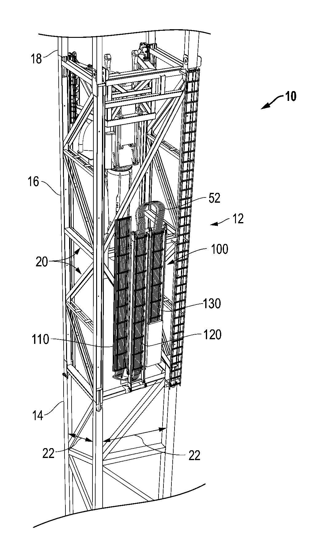
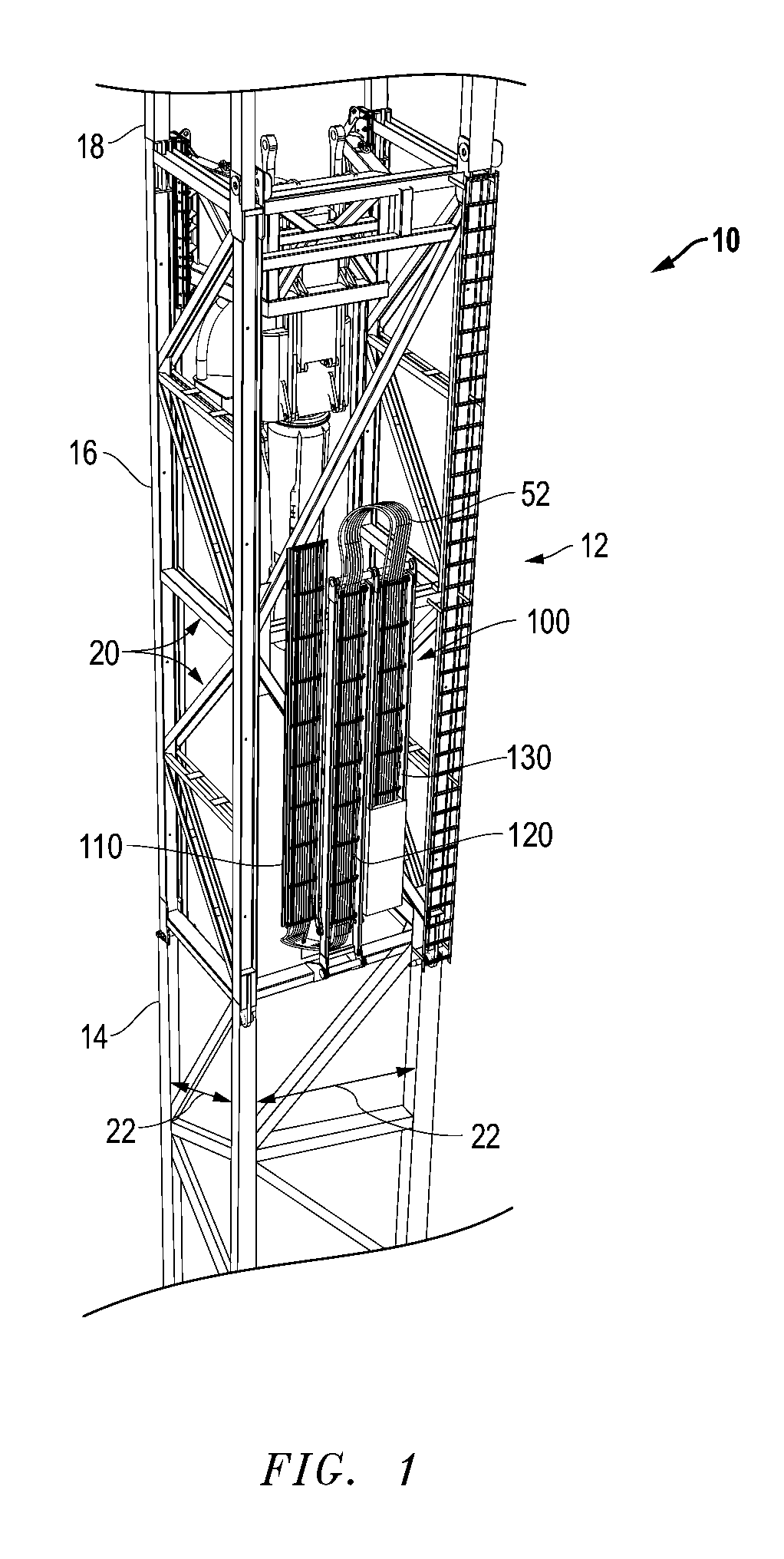
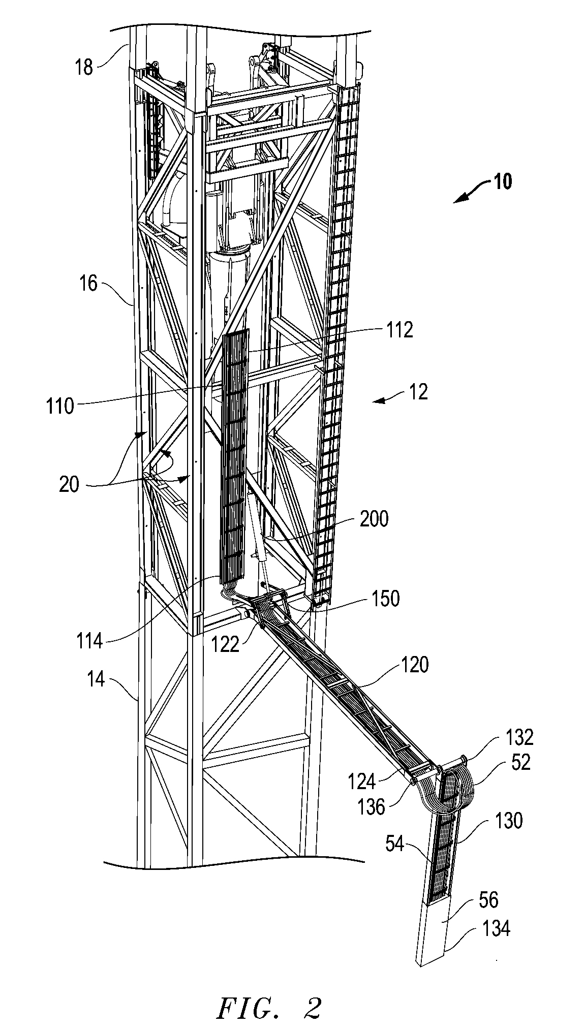
[0031]FIG. 1 is an isometric view of a cable tray assembly 100 of the present invention in a fully stowed position, shown mounted to a drilling rig 10. FIG. 2 illustrates cable tray assembly 100 in a partially deployed position. FIG. 3 illustrates cable tray assembly 100 in a fully deployed position.

[0032]As seen in FIGS. 1-3, extendable cable ...


PUM


Abstract

The present invention discloses a cable tray assembly for a drilling rig or other vertical structure. In one embodiment, an extendable cable tray assembly is provided for retractable attachment to a section of a mast of a drilling rig. The cable tray assembly includes an upper tray connected to the mast in a stationary relationship. A center tray has a pivot end pivotally connected to the mast, and an articulating end rotatable between a stowed position and a deployed position below, and offset to, the upper tray. A lower tray has an upper end and a lower end. The upper end is pivotally connected to the articulating end of the center tray. The lower tray is movable between a stowed position and a deployed position below, and offset to, the center tray. An actuator is provided such that extension and retraction of the actuator results in deployment and retraction of the cable tray assembly.

Description

TECHNICAL FIELD OF INVENTION[0001]The embodiments of the present invention relate to a new retractable cable tray system for transportation of cables used in association with large vertical structures, where transportation of the structure requires disassembly and separate transport. In particular, the present invention is applicable for rapid and safe consolidation of the numerous cables associated with a drilling rig mast, such that the cables can be retracted for transportation with a single mast section of a drilling rig without the need for multiple disconnections of the cable, or spooling of the cable for transportation.BACKGROUND OF THE INVENTION[0002]It is a common requirement in several industries to transport very long and heavy structures across the federal and state highways. As a particular example of such requirement, in the exploration of oil, gas and geothermal energy, drilling operations are used to create boreholes, or wells, in the earth. Drilling rigs used in sub...

Claims


Application Information

Patent Timeline
Patent Type & Authority Patents(United States)
IPC IPC(8): F16L3/00E21B15/00H02G3/04F16L3/26H02G3/00
CPCF16L3/26E21B15/00H02G3/0456H02G3/263
Inventor TREVITHICK, MARK W.ORGERON, KEITH J.
Owner T & T ENG SERVICES
Why Eureka
Try Eureka