
Lighting device and method of installing light emitter

a technology of light emitter and light source, which is applied in the field of general illumination, can solve the problems of incandescent light bulbs that are very energy-inefficient light sources, light emitting diodes incandescent light bulbs are relatively short life spans, so as to reduce or eliminate the need for frequent change-out, improve energy efficiency, and improve the effect of energy efficiency

Active Publication Date: 2015-10-06
IDEAL IND LIGHTING LLC
View PDF99 Cites 71 Cited by
  • Summary
  • Abstract
  • Description
  • Claims
  • Application Information

AI Technical Summary

Benefits of technology

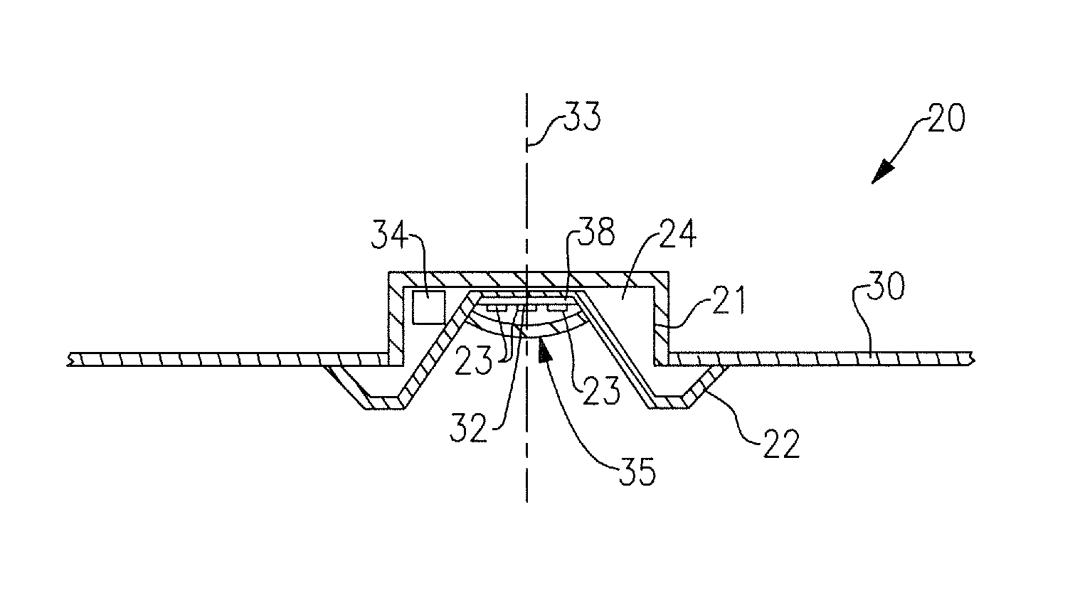
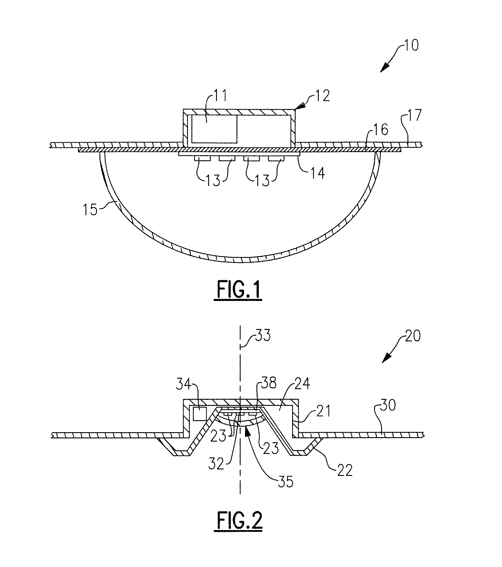
The patent is about a lighting device that can replace a dome light with a more energy-efficient and aesthetically pleasing lighting system that mimics the functionality of a recessed downlight. This device can be installed when a dome light is malfunctioning, to improve energy efficiency, or to reduce the need for frequent change-outs. It can also be used in new construction or to add lighting to existing construction where no lighting previously existed.

Problems solved by technology

It is well known that incandescent light bulbs are very energy-inefficient light sources; about ninety percent of the electricity they consume is released as heat rather than light.
Fluorescent light bulbs are more efficient than incandescent light bulbs (by a factor of about 10) but are still less efficient than solid state light emitters, such as light emitting diodes.
In addition, as compared to the normal lifetimes of solid state light emitters, e.g., light emitting diodes, incandescent light bulbs have relatively short lifetimes, i.e., typically about 750-1000 hours.
Fluorescent bulbs have longer lifetimes than incandescent lights (e.g., fluorescent bulbs typically have lifetimes of 10,000-20,000 hours), but provide less favorable color reproduction.
The impact of the need to replace light emitters is particularly pronounced where access is difficult (e.g., vaulted ceilings, bridges, high buildings, highway tunnels) and / or where change-out costs are extremely high.
Although the development of solid state light emitters (e.g., light emitting diodes) has in many ways revolutionized the lighting industry, some of the characteristics of solid state light emitters have presented challenges, some of which have not yet been fully met.
For example, solid state light emitters are commonly seen in indicator lamps and the like, but are not yet in widespread use for general illumination.
This solution, however, would typically require complete removal of the previous dome light fixture to install the new one.
(Utilizing LED lamps in a traditional dome light would generally result in the premature failure of those lamps, because incandescent dome lights are not constructed in a manner that would allow the LED lamps to run cool.)

Method used


Image

  • Lighting device and method of installing light emitter
  • Lighting device and method of installing light emitter
  • Lighting device and method of installing light emitter

Examples


Embodiment Construction

[0051]The present inventive subject matter now will be described more fully hereinafter with reference to the accompanying drawings, in which embodiments of the inventive subject matter are shown. However, this inventive subject matter should not be construed as being limited to the embodiments set forth herein. Rather, these embodiments are provided so that this disclosure will be thorough and complete, and will fully convey the scope of the inventive subject matter to those skilled in the art. Like numbers refer to like elements throughout.

[0052]As used herein the term “and / or” includes any and all combinations of one or more of the associated listed items.

[0053]The terminology used herein is for the purpose of describing particular embodiments only and is not intended to be limiting of the inventive subject matter. As used herein, the singular forms “a”, “an” and “the” are intended to include the plural forms as well, unless the context clearly indicates otherwise. It will be fur...


PUM

PropertyMeasurementUnit
lengthaaaaaaaaaa
temperatureaaaaaaaaaa
diameteraaaaaaaaaa

Abstract

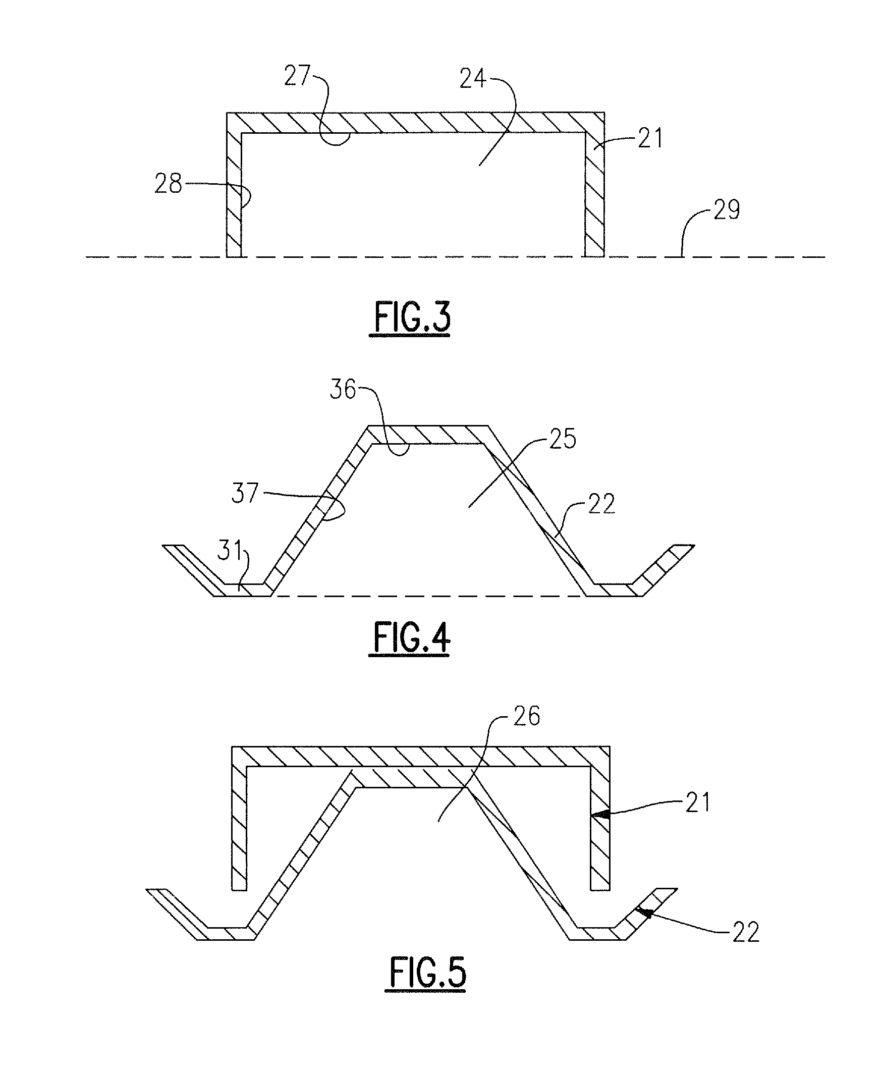
A lighting device comprising a junction box, a trim element and a solid state light emitter, at least a portion of a space defined by regions of the trim element within a space defined by regions of the junction box, the light emitter within the trim element space. A lighting device comprising a trim element (with at least two regions) and a solid state light emitter, in which at least a first part of the first region can be positioned in a first space with the second region outside the first space, the light emitter within the first part. A lighting device, comprising a trim element (which comprises at least two regions), part of an exterior of which defines a first space, at least a first part of the first region within the first space, a solid state light emitter within the first part. Methods of installing a light emitter.

Description

FIELD OF THE INVENTIVE SUBJECT MATTER[0001]The inventive subject matter relates to the field of general illumination. In some aspects, the inventive subject matter relates to a lighting device that comprises a trim element and one or more solid state light emitters. In some aspects, the inventive subject matter relates to a lighting device that comprises a trim element and at least a first solid state light emitter, in which the trim element comprises at least a first region that comprises at least a first concave portion, at least part of which can fit in a first space (in some aspects defined by a junction box), and in which the first solid state light emitter is within the first space. In some aspects, the inventive subject matter relates to a method of installing a light emitter, comprising inserting at least a first part of a first region of a trim element into a first space (in some aspects defined by a junction box), with a second region of the trim element outside the first ...

Claims


Application Information

Patent Timeline
Patent Type & Authority Patents(United States)
IPC IPC(8): F21V15/00F21V17/00F21S8/02F21V15/01F21V3/00F21Y101/02
CPCF21S8/026F21V15/01F21V3/00F21Y2101/02Y10T29/49002F21Y2115/10
Inventor PICKARD, PAUL KENNETHMEDENDORP, JR., NICHOLAS W.EDMOND, MARK D.LU, DONGPROGL, CURTDIXON, MARK
Owner IDEAL IND LIGHTING LLC
Learn More