Electrical connector plug having a metallic shield connected to an electrically conductive housing of the plug

a technology of electrical connectors and shields, which is applied in the direction of coupling devices, coupling protective earth/shielding arrangements, and two-part coupling devices, etc. it can solve the problems of large inconvenience for users, manufacturing difficulties for 3c product developers and accessory manufacturers, and troublesome maintenance of usb sockets built into computer hosts, so as to prevent elasticity loss, reduce manufacturing costs, and not easily damaged

Active Publication Date: 2015-10-06
ADVANCED CONNECTEK INC
View PDF5 Cites 16 Cited by
  • Summary
  • Abstract
  • Description
  • Claims
  • Application Information

AI Technical Summary

Benefits of technology

[0007]Various embodiments of the invention provide an electrical connector plug and conductive wire and an assembly provided with the same. Such embodiments prevent the resilient contact terminals from becoming a point of weakness in a USB socket, protecting and supporting the resilient contact terminals, so as to prevent structural damage due to excessive pressure. Various embodiments reduce the probability of malfunction related to contact terminals. Even if they are damaged, the user can easily change them, so as to save time and effort wasted by returning a device to the manufacturer for maintenance.
[0009]Another objective of various embodiments is to provide an electrical connector plug and conductive wire and an assembly provided with the same, which adds a metallic shield frame on the USB plug to provide additional protection for the vulnerable contact terminals. Excessive external force is absorbed by the metallic shield frame, so as to reduce the probability of damaging the structure of the contact terminals.
[0010]Another aspect provides an electrical connector plug and conductive wire and an assembly provided with the same, which adds a metallic shield frame to a USB plug to provide crosstalk protection.
[0011]Yet another aspect is to provide an electrical connector plug and conductive wire and an assembly provided with the same, wherein the shell of the USB plug that typically goes through a bending process for several times is replaced by an electrically conductive section extending from the frame section of the metallic shield frame formed by casting, so as to reduce the manufacturing costs of the USB plug.
[0015]Various embodiments of the electrical connector plug, conductive wire and assembly provided with the same mount the resilient electrically conductive terminals on the USB plug, and provide a metallic shield frame formed by metallic casting to support resilient contact terminals, thus preventing elasticity loss due to excessive pressure. Moreover, it replaces the electrically conductive lip that typically must go through a bending process several times, strengthening the electrical connection between the USB plug and the USB socket, and also reduces manufacturing costs. In this way, various embodiments provide additional protection for the resilient contact terminals on the USB plug, so that they are not easily damaged. Even if the resilient contact terminals are damaged, the user does not have to take the host device in for repair, but just needs to change the spare USB accessories, or even the conductive wire only. In this respect, the structure improves upon a serious drawback of the prior art USB socket and increases its durability, eliminating the trouble of repair by the manufacturer for the users.

Problems solved by technology

This can be the source of great inconvenience for the user.
In addition, this introduces manufacturing difficulties for 3C product developers and accessory manufacturers.
To date, the development of the USB technology has gone through three major phases, from 1.0 to 3.0, and it is somewhat troublesome to change and maintain the USB socket built into the computer host.
However, the resilient electrically conductive terminals may suffer from elastic fatigue, over-forcing or over-displacement, which can interrupt the electrical connection between the contact terminals and the resilient electrically conductive terminals.
Powered-off or short-circuited USB device obviously cannot work effectively, which is, again, a source of great inconvenience to users.
Worse, this repeated plugging / unplugging operation may damage the external device more easily, and so users should be more cautious.
However, it is quite difficult for users to change the USB socket by themselves, which typically requires disassembling the 3C product and checking the motherboard.
For most common users, who are unfamiliar with the internal structure of 3C products, they can only return the product to the manufacturer to change the USB socket, and this may take several days.
Nowadays, people rely on 3C products so much that they may become annoyed if so much time is wasted on a small component, which introduces unwanted delays in their work or entertainment.
Unavoidably, the resilient electrically conductive terminals of USB 3.0 are still the core components susceptible to damage.
However, the overall structure of USB 3.0 is quite delicate, and so it is both time and energy consuming to do this on the delicate structure of a USB 3.0 device for the above purpose, which increases unnecessary manufacturing costs.

Method used


Image

  • Electrical connector plug having a metallic shield connected to an electrically conductive housing of the plug
  • Electrical connector plug having a metallic shield connected to an electrically conductive housing of the plug
  • Electrical connector plug having a metallic shield connected to an electrically conductive housing of the plug

Examples


Embodiment Construction

[0026]The above statements related to the invention, other technical contents, features and benefits will be clearly presented in the detailed illustration for the preferred embodiments as shown in the diagrams. Additionally, similar assemblies in these embodiments will be represented by similar symbols.

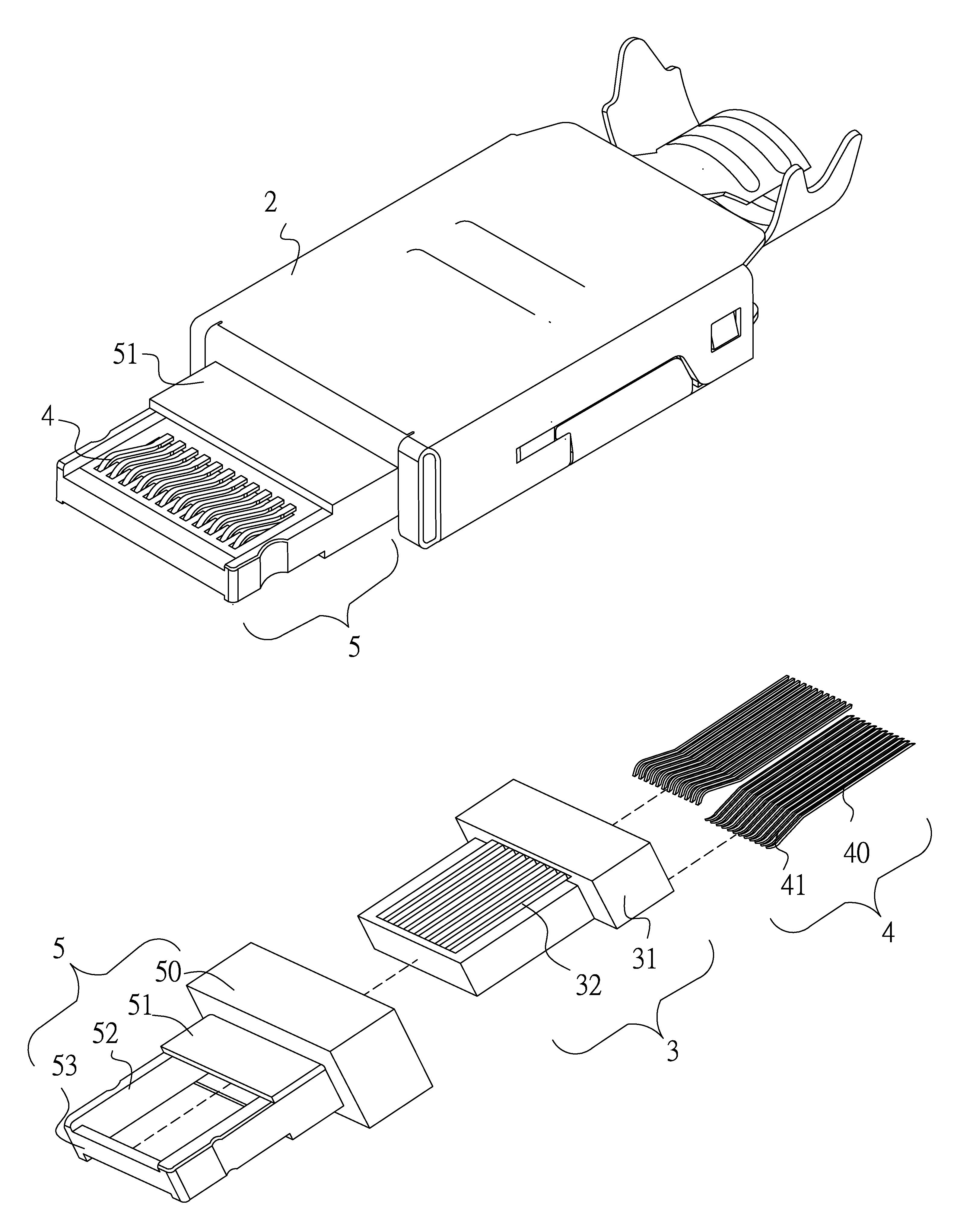
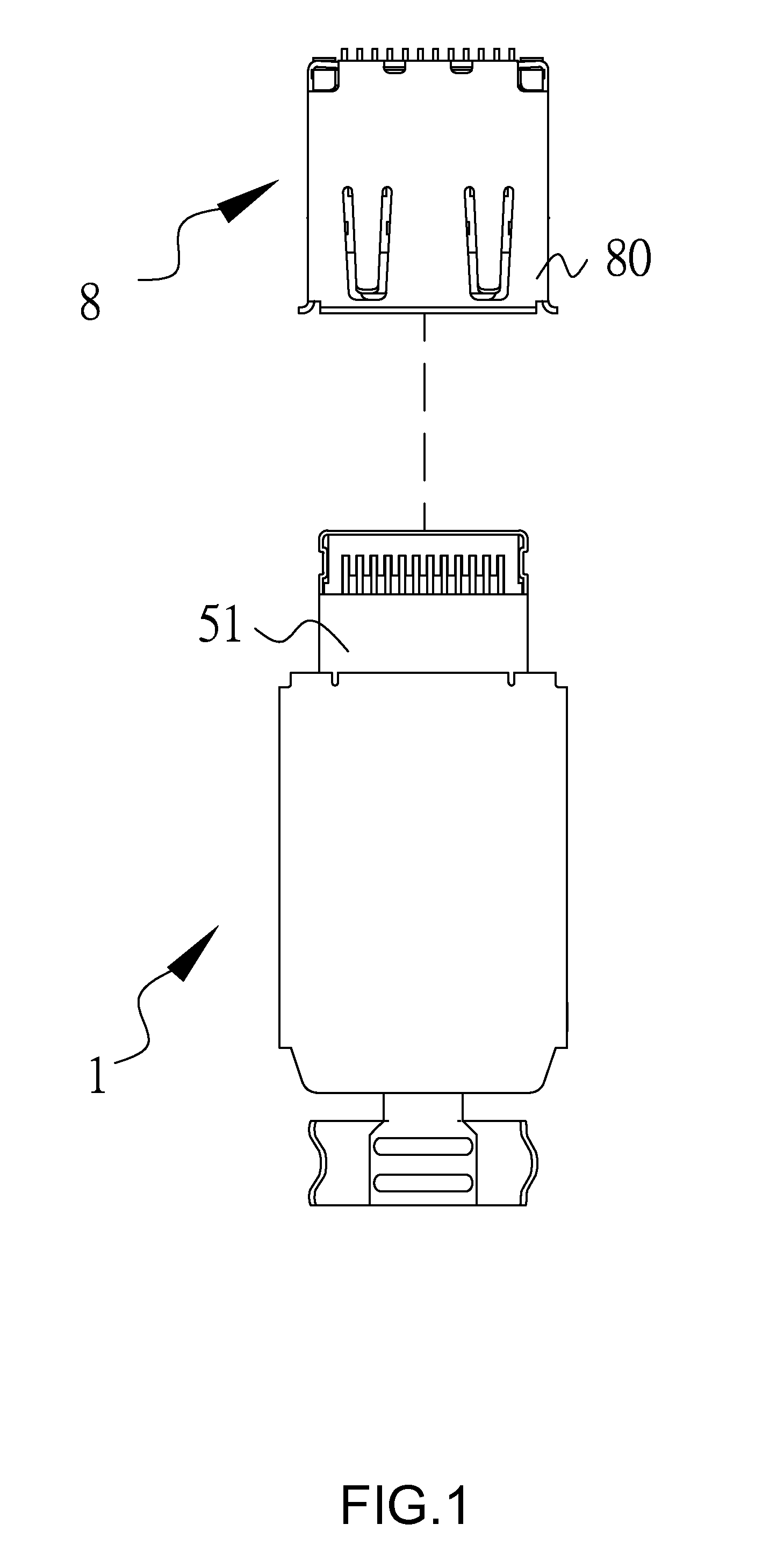
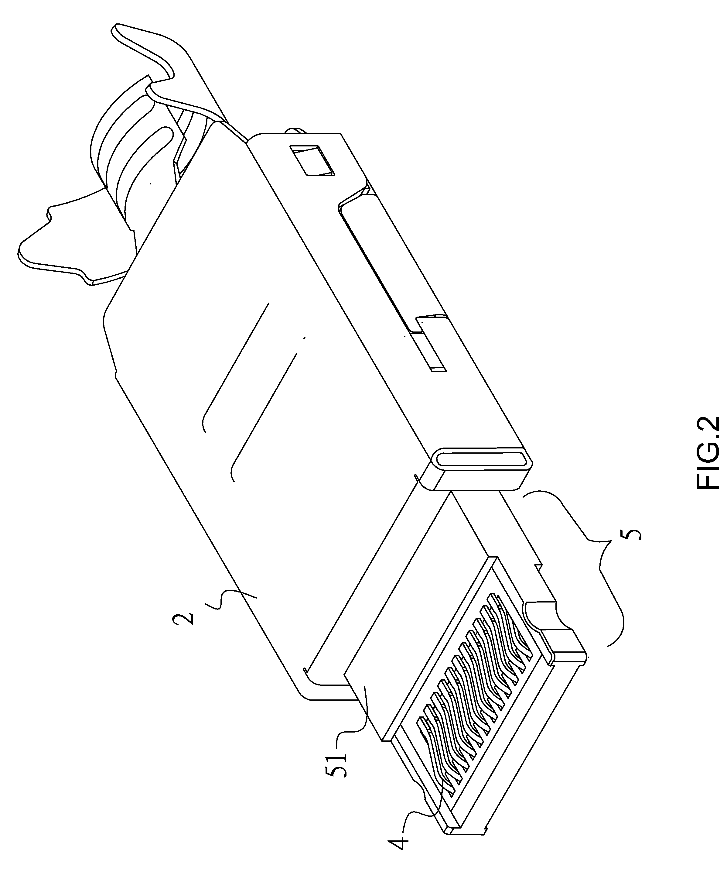
[0027]A first embodiment utilizes an electrical connector assembly as an example, as shown in FIGS. 1-6. The electrical connector assembly is a USB connector assembly in this embodiment, comprised of an electrical connector socket 8 which is a USB socket and an electrical connector plug 1 which is a USB plug. An electrically conductive section 51 extends from the frame section 50 of the metallic shield frame 5 towards the front section 53, and is adapted for electrical connection to the casing 80 of the electrical connector socket 8. When the electrical connector plug 1 is coupled to the electrical connector socket 8, their metallic materials are electrically connected. The electrica...


PUM


Abstract

An electrical connector plug having resilient contact terminals electrically connects to an electrical connector socket with a casing and two groups of engaging terminals mounted on or in the casing. The electrical connector plug has an electrically conductive housing. A coupling device extends in a longitudinal direction and has a base portion. Two groups of resilient contact terminals are mounted in the coupling device axially symmetrically arranged with each other in the longitudinal direction, each of which has a flat section and an upwardly protruding contact section. A metallic shield frame is electrically connected to and secured to the electrically conductive housing, having a frame section, a front section, and two lateral protective sections. An electrically conductive section extends from the frame section towards the front section for electrical connection to the casing of the electrical connector socket.

Description

FIELD OF THE INVENTION[0001]The present invention relates to an electrical connector plug and conductive wire and an assembly provided with the same, and more particularly, to an electrical connector plug adapted for the Universal Serial Bus (USB) interface.BACKGROUND OF THE INVENTION[0002]To increase the flexibility of 3C products (computers / communications / consumer products), various external devices can be connected using multi-media slots provided on the 3C products, to support devices such as external hard drives, portable disks or memory sticks (collectively referred to herein as USB drives), multi-media video & audio equipment, keyboards and so forth, so as to functional expansion of the 3C product. However, when 3C products initially came to rise, manufacturers designed various proprietary specifications for the transmission or communication interfaces for their own external devices. For example, many printers can only be connected to LPT ports, many MODEMs can only be connec...

Claims


Application Information

Patent Timeline
Patent Type & Authority Patents(United States)
IPC IPC(8): H01R13/658H01R13/504H01R13/6581H01R13/6597H01R24/62
CPCH01R13/504H01R13/6581H01R13/6597H01R13/65802H01R24/62H01R13/658
Inventor KAO, YA-FENTSAI, YU-LUNHOU, PIN-YUANWANG, WEN-YUTSAI, WEN-HSIEN
Owner ADVANCED CONNECTEK INC
Why Eureka
Try Eureka