Golf club head

a golf club and head technology, applied in golf clubs, golf, sport apparatus, etc., can solve the problem of the center of gravity of the head being moved to the heel side, and achieve the effect of suppressing the center of gravity and lowering the center of gravity

Inactive Publication Date: 2015-10-13
SUMITOMO RUBBER IND LTD
View PDF22 Cites 11 Cited by
  • Summary
  • Abstract
  • Description
  • Claims
  • Application Information

AI Technical Summary

Benefits of technology

[0006]A usual head has a neck part as a joining portion of the head and a shaft. A shaft hole is formed in the neck part. In respect of securing the adhesion area of the head and the shaft, there is a limit to shorten the length of the neck part. The neck part is located on a heel side, and extends upward. Therefore, the mass of the neck part is apt to cause deviation of the position of the center of gravity of the head to the heel side. The mass existing in the upper part of the neck part may inhibit the lowering of the center of gravity.
[0007]It is an object of the present invention to provide a golf club head which can suppress maldistribution of a center of gravity of the head to a heel side and which can lower the center of gravity.
[0015]The maldistribution of the center of gravity of the head on the heel side can be suppressed and lowering the center of gravity can be achieved.

Problems solved by technology

Therefore, the mass of the neck part is apt to cause deviation of the position of the center of gravity of the head to the heel side.

Method used


Image

  • Golf club head
  • Golf club head
  • Golf club head

Examples


examples

[0086]Hereinafter, the effects of the present invention will be clarified by examples. However, the present invention should not be interpreted in a limited way based on the description of examples.

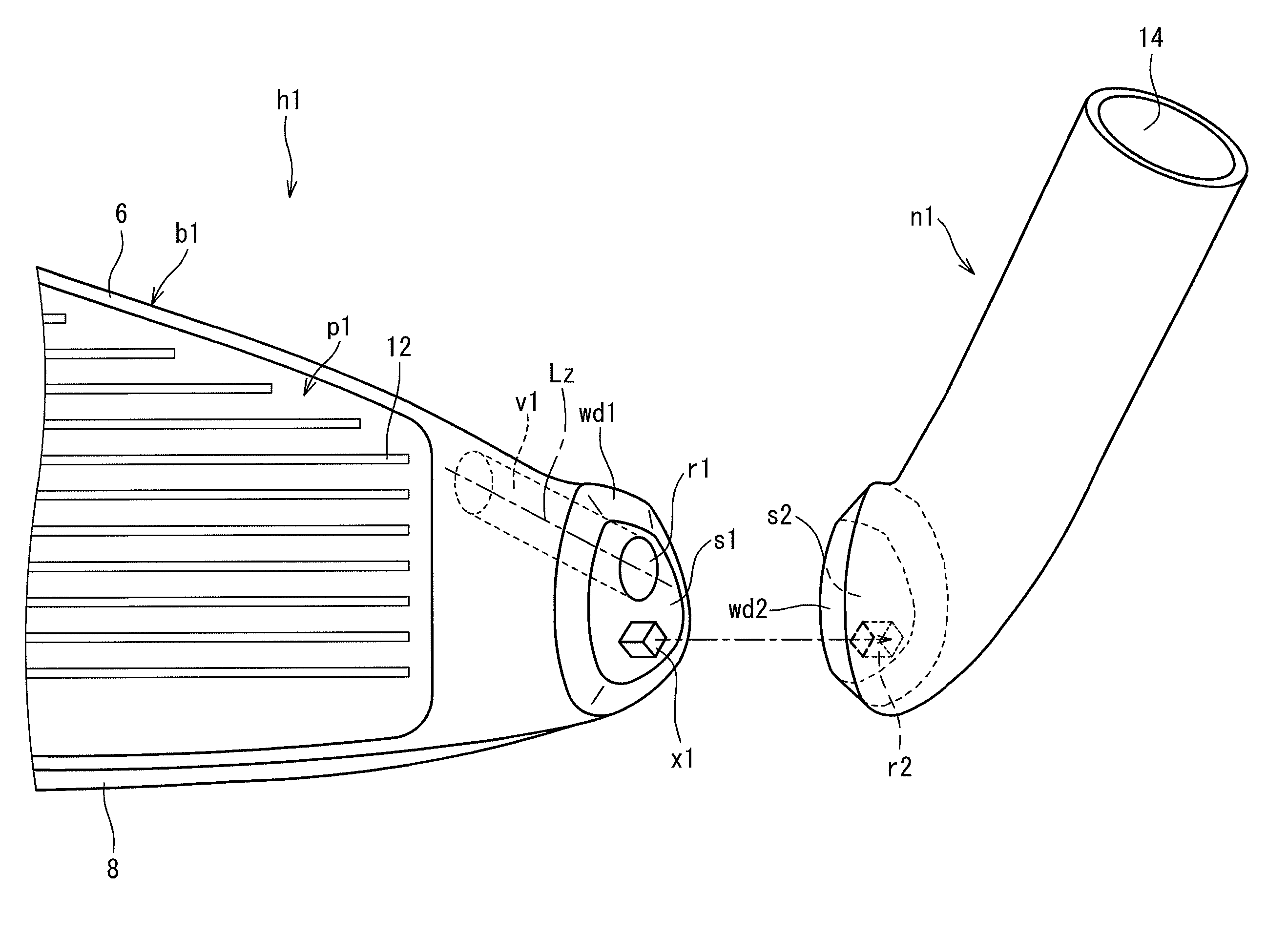
[0087]A head having the same structure as that of the head 2 was produced. A body of the head was produced by a lost-wax precision casting method. A first recessed part r1 was formed by casting. The material of the body was SUS630. The material of a face plate was a titanium alloy “51AF” manufactured by Nippon Steel Corporation. A neck part was produced by the lost-wax precision casting method. The material of the neck part was a tungsten-nickel alloy. A weight member was produced by the lost-wax precision casting method. The material of the weight member was a tungsten-nickel alloy. The neck part was welded to the head body by the method described using FIG. 6 to obtain the head. In the head, the first recessed part was closed by a neck side joint surface, and a space v1 having a large v...


PUM


Abstract

A head 2 includes a head body h1 and a neck part n1. The head body h1 and the neck part n1 are joined. The head body h1 has a body side joint surface s1 and a first recessed part opened in the body side joint surface s1. A space v1 is formed by the first recessed part r1. The neck part n1 has a neck side joint surface brought into surface contact with the body side joint surface s1 and a shaft hole 14. An abutted boundary surface Pt passes through a vicinity ad1 of a head height lowest point. When a plane perpendicular to an axis line z of the shaft hole 14 is defined as PL, and an angle between the plane PL and the abutted boundary surface Pt is θ degree, the angle θ is a plus value.

Description

[0001]The present application claims priority on Patent Application No. 2012-042619 filed in JAPAN on Feb. 29, 2012, the entire contents of which are hereby incorporated by reference.BACKGROUND OF THE INVENTION[0002]1. Field of the Invention[0003]The present invention relates to a golf club head.[0004]2. Description of the Related Art[0005]A golf club head obtained by joining two members has been known. Japanese Patent Application Laid-Open No. 2002-165908 (US2002 / 0034984) discloses a head obtained by joining a hosel base part and a hosel body. In the head, a hollow part is formed in a hosel or a heel. Japanese Utility Model Application Publication No. 3142188 (US2009 / 0111604) discloses a head obtained by joining a body made of a first material and a neck part made of a second material in FIGS. 2A and 2B.SUMMARY OF THE INVENTION[0006]A usual head has a neck part as a joining portion of the head and a shaft. A shaft hole is formed in the neck part. In respect of securing the adhesion...

Claims


Application Information

Patent Timeline
Patent Type & Authority Patents(United States)
IPC IPC(8): A63B53/04A63B53/02A63B59/00A63B102/32
CPCA63B53/02A63B53/047A63B53/0466A63B53/0487A63B2053/0491A63B2053/042A63B2053/0408A63B2053/0433A63B59/60A63B60/50A63B53/0408A63B53/042A63B53/0433A63B53/04A63B60/00
Inventor UEDA, NAOYOSHIMIZUTANI, NARUHIRO
Owner SUMITOMO RUBBER IND LTD
Why Eureka
Try Eureka