Sheet conveying apparatus and image forming apparatus

a conveying apparatus and forming apparatus technology, applied in the direction of article feeders, thin material processing, transportation and packaging, etc., can solve the problems of large rigidity, easy sheet clogging, and significant increase in cost, so as to reduce the size, reduce the constant of springs, and stabilize the spring pressure

Active Publication Date: 2015-10-13
CANON KK
View PDF21 Cites 4 Cited by
  • Summary
  • Abstract
  • Description
  • Claims
  • Application Information

AI Technical Summary

Benefits of technology

[0009]An object of the invention is to provide a sheet conveying apparatus and an image forming apparatus which is provided with the same, through which a size can be reduced and a spring constant is reduced, and a spring pressure can be stabilized by suppressing a variation in pressure.
[0011]According to the invention, it is possible to reduce the apparatus in size and reduce the spring constant, and it is possible to make the spring pressure stable by suppressing the variation in pressure. Furthermore, the facing portion of the holding portion can be maintained in substantially parallel to the conveying guide by a frictional force between the holding portion and the pressing spring. In addition, since the spring pressure is stabilized by suppressing the variation in pressure, it is possible to prevent clogging and skew feeding of the sheet.

Problems solved by technology

In particular, there has been increasing demand for a thick sheet used in packages made of a boxing material as a wide variety of sheets, but the sheet has a problem in that rigidity is large and sheet clogging easily occurs.
However, when the radius R of the bending portion in the conveying path is made large, the apparatus is increased in size to cause the cost to be significantly increased, so that it conflicts with reality.

Method used


Image

  • Sheet conveying apparatus and image forming apparatus
  • Sheet conveying apparatus and image forming apparatus
  • Sheet conveying apparatus and image forming apparatus

Examples


Embodiment Construction

[0023]Hereinafter, exemplary embodiments of the invention will be described in detail with reference to the drawings. However, dimensions, materials, and shapes of the components, and relative arrangements therebetween described in the following embodiments may be appropriately changed according to the configuration and various conditions of the apparatus to which the invention is applied. Therefore, if not otherwise specified, it is not intended to limit the scope of the invention only to these configurations.

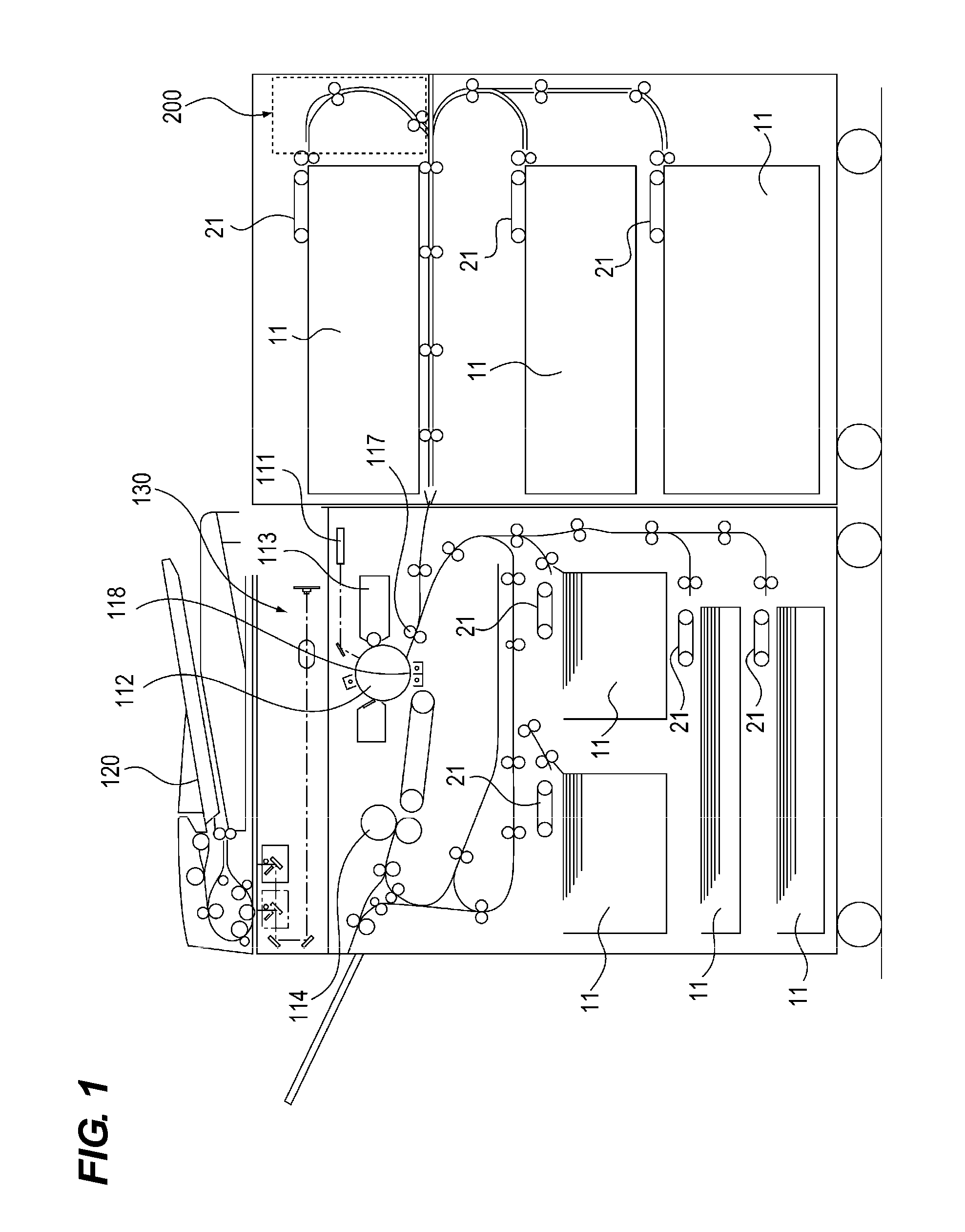
[0024]An image forming apparatus which includes a sheet conveying apparatus according to the example will be described using FIG. 1. FIG. 1 is a schematic sectional view of the image forming apparatus which includes the sheet conveying apparatus to which the invention is employed.

[0025]First, an original is automatically sent up to a reading position by an auto original feeding portion 120, and image information is read by an image reading portion 130. The read image informati...


PUM


Abstract

A sheet conveying apparatus includes a conveying guide configured to guide a sheet which is conveyed by a conveying roller and a driven roller, a pressing spring configured to press the driven roller toward the conveying roller, a holding portion configured to be provided to be rotated about a shaft center of the driven roller and to receive a pressing force of the pressing spring, and a supporting portion configured to support the driven roller in a direction perpendicular to a sheet conveying direction to abut on or be separated from the conveying roller. The holding portion includes a facing portion which is disposed to face the conveying guide. The facing portion is separated from the conveying guide in a state where the driven roller abuts on the conveying roller. The facing portion abuts on the conveying guide when the driven roller is separated from the conveying roller.

Description

BACKGROUND OF THE INVENTION[0001]1. Field of the Invention[0002]The present invention relates to a sheet conveying apparatus which conveys a sheet, and an image forming apparatus which is provided with the sheet conveying apparatus.[0003]2. Description of the Related Art[0004]In recent years, when an image forming apparatus such as a printer or a copying machine performs a printing operation, a wide variety of sheets are used depending on purposes. In particular, there has been increasing demand for a thick sheet used in packages made of a boxing material as a wide variety of sheets, but the sheet has a problem in that rigidity is large and sheet clogging easily occurs. Therefore, as a countermeasure, a radius R of a bending portion in a conveying path is made large, resistance exerted from a conveying guide when the sheet is conveyed is reduced, and a nip pressure of a conveying roller is significantly increased to raise a conveying force.[0005]Furthermore, in order to comply with ...

Claims


Application Information

Patent Timeline
Patent Type & Authority Patents(United States)
IPC IPC(8): B65H5/02B65H5/06B65H5/04
CPCB65H5/068B65H5/062B65H2404/15212B65H2404/144B65H2404/152B65H2402/45B65H2402/441B65H2404/1113B65H2404/1341B65H2404/174B65H2404/6111B65H2405/15B65H2405/332B65H2801/06B65H2402/54
Inventor INOUE, HIROSHIGE
Owner CANON KK
Why Eureka
Try Eureka