
Method for supporting SNCP over packet network

a packet network and packet technology, applied in the field of high-availability telecommunication networks, can solve the problems of affecting the protection level, the complexity of the protection scheme, and the impact of the protection in other sub-networks

Active Publication Date: 2015-10-13
ORCKIT IP LLC
View PDF7 Cites 2 Cited by
  • Summary
  • Abstract
  • Description
  • Claims
  • Application Information

AI Technical Summary

Benefits of technology

The present invention provides a method for supporting protection of data traffic in a network having a packet switched sub-network. The method ensures that failure of a path in one sub-network does not affect protection offered at another sub-network. The network is configured with a first and second sub-network, which communicate through a packet switched network. The first and second sub-network protocols are selected from a group consisting of SDH and SONET. The first sub-network provides protection services using either SNCP or UPSR, while the second sub-network provides protection services using either SNCP or UPSR. The network also allows for failure protection at the sub-network level, repairing path failures in individual sub-networks without affecting protection in another sub-network. The method includes configuring path protection and defining the protocols for the first and second sub-networks. Overall, the invention provides improved resilience and protection of data traffic in network configurations.

Problems solved by technology

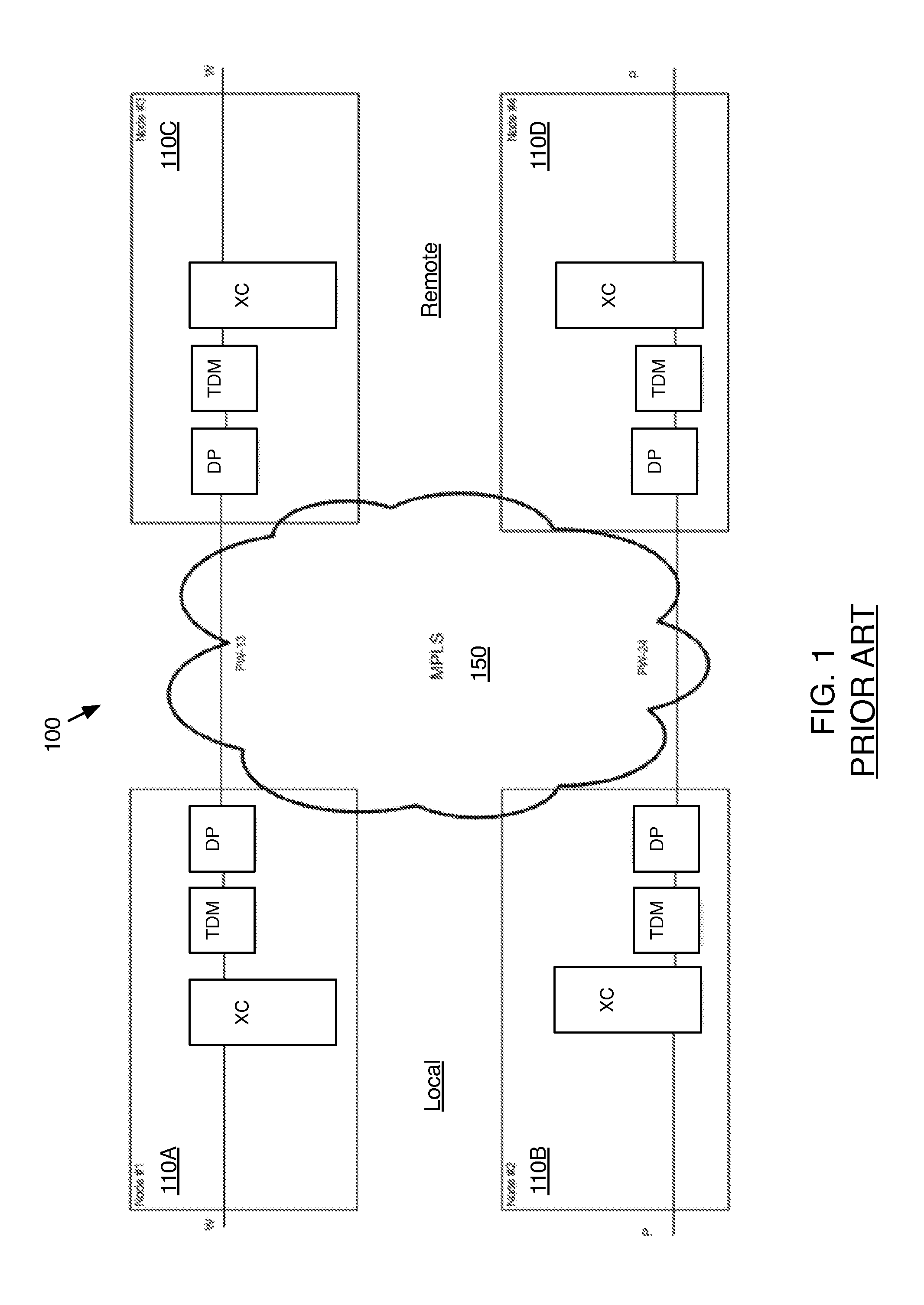
While this provided the advantages of greater efficiency in terms of more usage of each physical circuit, the tradeoff was occasional quality issues, such as latency if a particular circuit was over utilized.
Using DNI in SNCP applications may cause additional complexity in the protection scheme, as SNCP and UPSR provide protection against a single failure in each sub-network, and DNI also protects against interconnecting failures.
By repairing failures in the sub-network level, a failure in one sub-network may not be contained within the sub-network, thus impacting protection in other sub-networks.
In this case, a failure in the MPLS sub-network affects the level of protection in the interconnected SDH sub-network, such that the protection scheme does not protect against a single failure in each sub-network.

Method used


Image

  • Method for supporting SNCP over packet network
  • Method for supporting SNCP over packet network
  • Method for supporting SNCP over packet network

Examples


first embodiment

2×2 Configuration

[0035]Among other possible embodiments, in a first exemplary embodiment of a method of supporting SNCP over packet networks, a packet sub-network is connected to two SDH sub-networks and transports one or more SDH paths that are SNCP-protected in both SDH sub-networks. In this embodiment, the packet sub-network connects to each of the two sub-network interconnection points by a working path and a protection path.

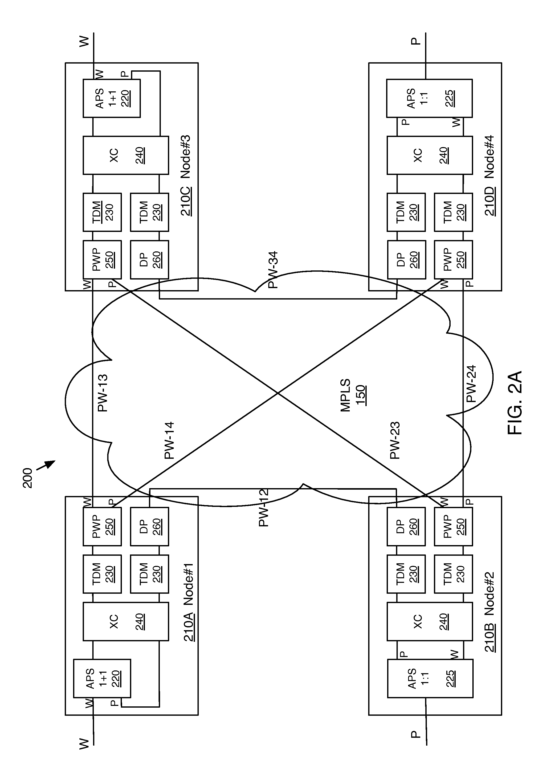
[0036]FIG. 2A is a schematic diagram of a second network 200 having four SNCP terminating nodes 210 including a first node 210A, a second node 210B, a third node 210C and a fourth node 210D. The first node 210A and the second node 210B are part of a first sub-network, and the third node 210C and the fourth node 210D are part of a second sub-network. The nodes 210 may be SNCP terminating equipment (STE), examples of which include, but are not limited to, add / drop multiplexers. The first sub-network and the second sub-network may be, for example, counter rotat...

second embodiment

2×2 Configuration with Single Node SDH

[0051]A second exemplary embodiment of a method of supporting SNCP over packet networks is shown in FIG. 3. In general, the second embodiment is similar to the first embodiment, except that according to the second embodiment, the interconnection between the MPLS sub-network 150 with the first SDH sub-network and / or the second SDH sub-network takes place over a single node, as opposed to DNI.

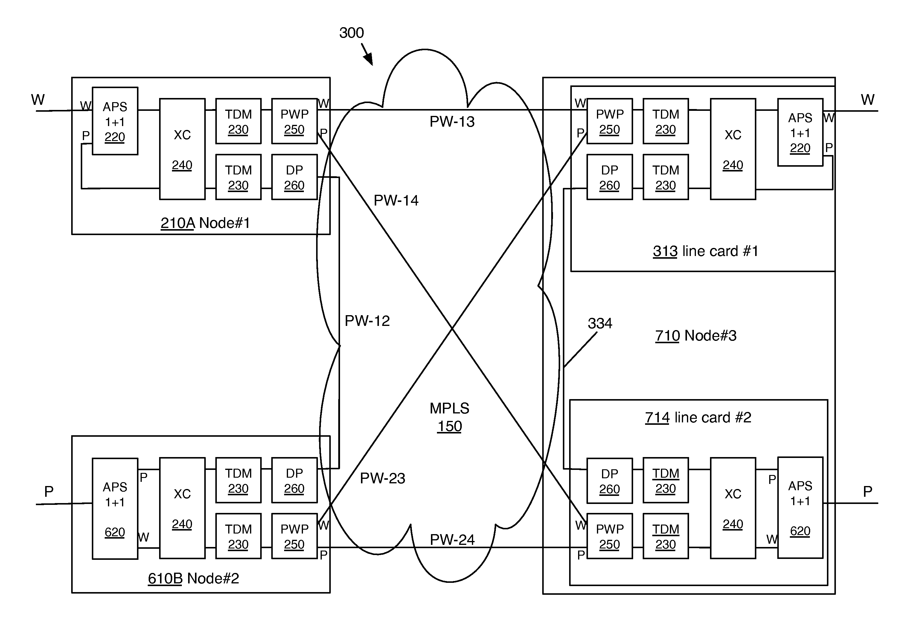
[0052]FIG. 3 is a schematic diagram of a third network 300 having three SNCP terminating nodes including a first node 210A, a second node 210B, and a third node 310. The first sub-network deploys a DNI connection with the MPLS sub-network 150. The first node 210A and the second node 210B are part of a first sub-network, and the third node 310 is part of a second sub-network. Unlike the first embodiment, under the second embodiment the second sub-network provides two working / protection connection pairs to the MPLS sub-network at a single node, the third node 3...

third embodiment

2×1 Configuration

[0056]In a third exemplary embodiment of a method of supporting SNCP over packet networks, here called the 2×1 scenario, a packet network is connected to two SDH sub-networks and carries an SDH path that is SNCP-protected in only one of the SDH sub-networks. In the third embodiment, the packet node is connected to two paths (working and protection) in one of the sub-network interconnection points, and to a single path in the other. As with the first and second embodiments, the packet sub-network is configured to provide the same type of path protection as an SDH sub-network using SNCP.

[0057]FIG. 4A is a schematic diagram of a fourth network 400 having three SNCP terminating nodes 410 including a first node 410A, a second node 410B, and a third node 410C. The first sub-network deploys a DNI connection with the MPLS sub-network 150. The first node 410A and the second node 410B are part of a first sub-network, and the third node 410C is part of a second sub-network. Un...


PUM


Abstract

A method is presented for supporting SNCP over a packet network connecting to two SDH sub-networks and transporting one or more SDH paths that are SNCP-protected in both SDH sub-networks. The packet network connects to each of two sub-network interconnection points by a working path and a protection path. The packet sub-network may provide the same type of path protection as an SDH sub-network using SNCP, while avoiding bandwidth duplication.

Description

FIELD OF THE INVENTION[0001]The present invention relates to telecommunications, and more particularly, is related to high availability telecommunication networks.BACKGROUND OF THE INVENTION[0002]Traditional analog voice telecommunication was carried over dedicated circuits, so that each connection used the full bandwidth of a circuit. With the advent of digital telecommunications, data and voice messages became packetized, so that a physical circuit may carry multiple virtual circuits. While this provided the advantages of greater efficiency in terms of more usage of each physical circuit, the tradeoff was occasional quality issues, such as latency if a particular circuit was over utilized.[0003]Synchronous Digital Hierarchy (SDH) and synchronous optical network (SONET) were originally developed to transport voice and data over dedicated fiber optic cables. Several methods exist for transmitting SDH / SONET signals over packet networks using pseudo wires (PW), such as Circuit Emulati...

Claims


Application Information

Patent Timeline
Patent Type & Authority Patents(United States)
IPC IPC(8): H04B10/00H04L12/703H04L12/939H04B10/032H04L12/721H04L45/28
CPCH04B10/032H04L49/557H04L45/68H04L45/28H04L45/24H04L15/28H04Q11/0066H04Q2011/0081
Inventor COHN, DANIELRAM, RAFI
Owner ORCKIT IP LLC
Learn More